A roller cone bit

A roller cone bit and roller cone technology are applied in drill bits, earth-moving drilling, drilling equipment and other directions, which can solve the problems of poor cutting effect and short service life, and achieve the effects of improving service life, improving efficiency and improving uniformity.

Inactive Publication Date: 2019-04-09
成都锐钻钻头制造有限公司
View PDF6 Cites 0 Cited by
  • Summary
  • Abstract
  • Description
  • Claims
  • Application Information

AI Technical Summary

Problems solved by technology

[0008] In order to solve the problems of short service life and poor cutting effect existing in the existing single cone bit, the present invention provides a cone bit, which can adjust the position of each cutting tooth during use, so that each row on the cone can cut The teeth can be cut at different positions to improve the uniformity of cutting of each cutting tooth; at the same time, the adhesion on the cutting teeth can be cleaned to improve the cutting effect; and the arrangement of the cutting teeth can improve the relationship between the cutting teeth and the rock mass. tension, thereby improving the cutting effect

Method used


Image

  • A roller cone bit
  • A roller cone bit
  • A roller cone bit

Examples


Embodiment Construction

[0034] The present invention will be further described below in conjunction with the embodiments, and the described embodiments are only a part of the embodiments of the present invention, not all of them. Based on the embodiments of the present invention, other used embodiments obtained by persons of ordinary skill in the art without creative efforts all belong to the protection scope of the present invention.

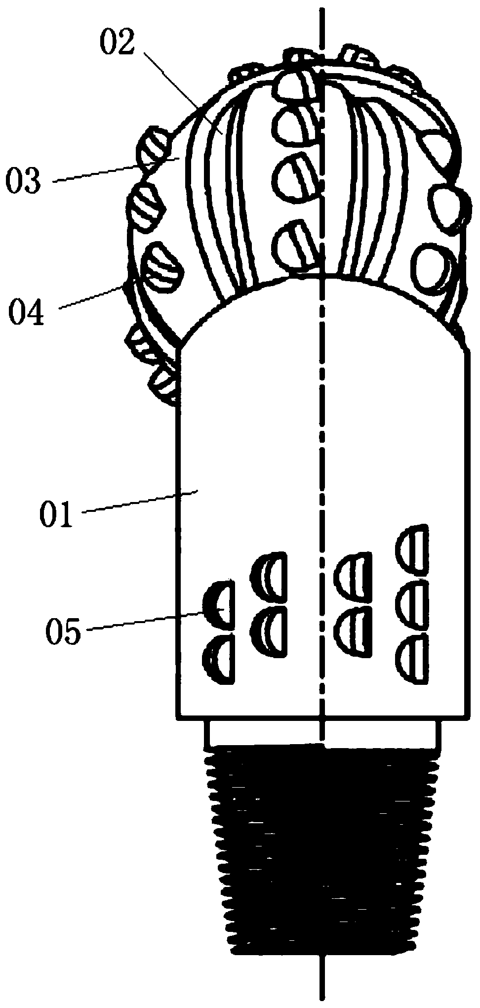
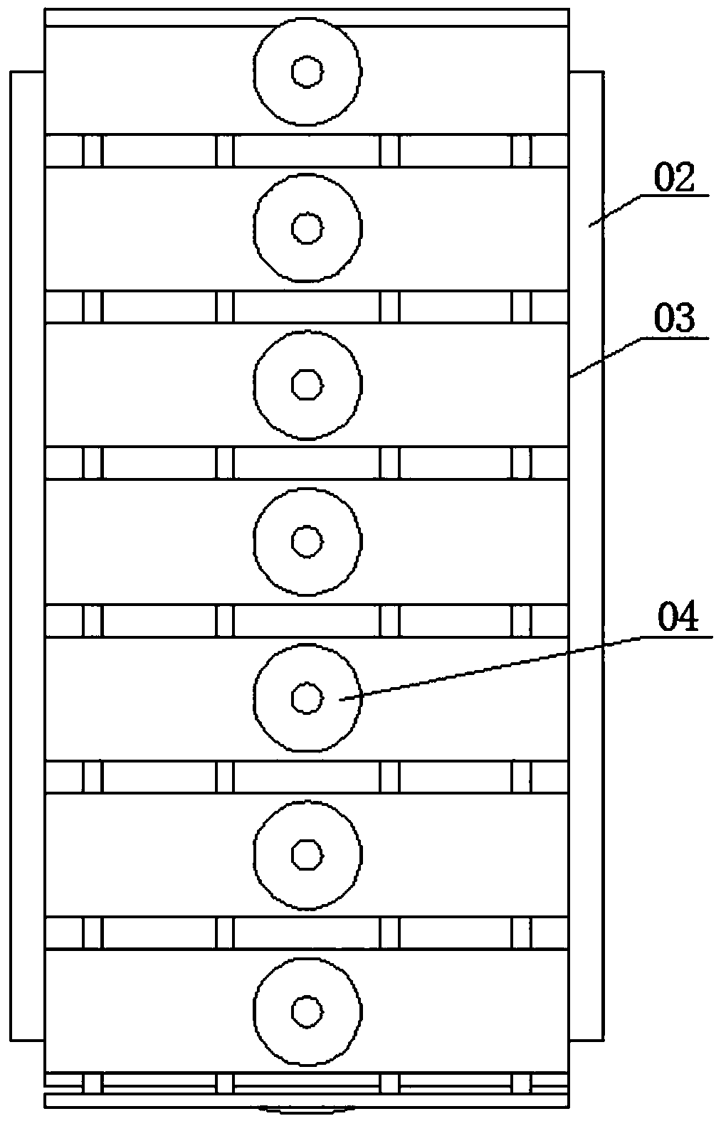
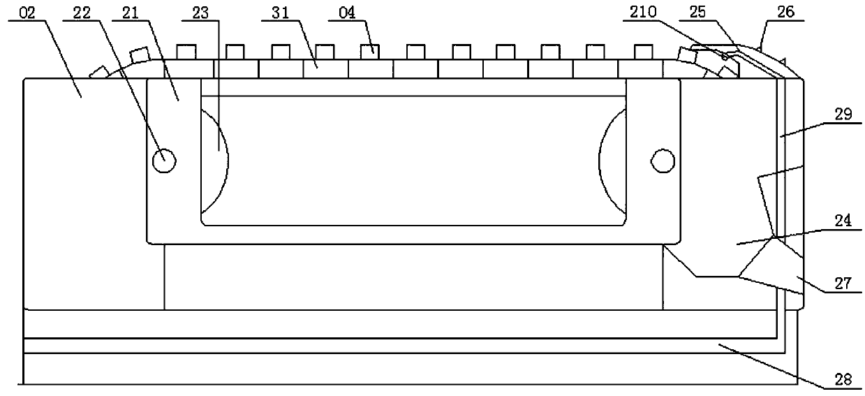
[0035]In conjunction with the accompanying drawings, the roller cone bit of the present invention includes a base body 01, on which the base body 01 is rotatably connected with a cone wheel 02, wherein the base body 01 is provided with gage teeth 05, as a preferred mode of the present invention, on the base body 01 At least two rows of gage teeth 05 are provided, and a plurality of installation grooves are evenly arranged on the outer circumference of the cone 02, wherein a cutting groove is formed on the outer surface of the cone between adjacent installation grooves,...


PUM


Abstract

The invention belongs to the technical field of drill bits and discloses a roller bit to solve the problem of short service life and poor cutting performance of the existing single-cone roller bits. The roller bit comprises a base; a roller cone is connected to the base; a mounting groove is installed on an external circumference of the roller cone; the mounting groove sleeves a mounting plate; the mounting plate is provided with multiple cutting teeth; a rotating direction of the mounting plate is vertical to the rotating direction of the roller cone; a roller cone end part away from the baseis provided with a protecting cover; a vertical gap is formed between the inner wall of the protecting cover and an external rim of the cutting teeth which is rotating to the place;; the roller coneis provided with a cooling liquid channel; the protecting cover is provided with a liquid outlet channel which is connected with the cooling channel therein; the liquid outlet channel is provided witha nozzle facing the cutting teeth; the cutting teeth on each mounting plate are spiral type; the spiral direction of the formation of each cutting tooth is from the root of the roller cone to the tipof the roller cone.

Description

technical field [0001] The invention belongs to the technical field of drill bits, in particular to a roller cone bit. Background technique [0002] The roller cone bit is the most widely used type of drilling bit. When the roller cone bit is working, the cutting teeth alternately contact the bottom of the well, the rock-breaking torque is small, the contact area between the cutting teeth and the bottom of the well is small, the specific pressure is high, and it is easy to penetrate into the formation; the total length of the working blade is large, so the wear is relatively reduced. Roller cone bits can adapt to a variety of formations from soft to hard. [0003] According to the number of cones, it can be divided into single-cone bits, three-cone bits and assembled multi-cone bits. According to the cutting material, it can be divided into steel teeth (milling teeth) and toothed gear bits. [0004] As a tool for drilling rock formations, the roller cone bit has been wide...

Claims


Application Information

Patent Timeline
Patent Type & Authority Patents(China)
IPC IPC(8): E21B10/08E21B10/16E21B10/18E21B10/20
CPCE21B10/08E21B10/16E21B10/18E21B10/20
Inventor 易勇
Owner 成都锐钻钻头制造有限公司
Why Eureka
Try Eureka