Simple measuring device capable of accurately measuring slab thickness of floor slab

A technology of precise measurement and measuring instruments, which is applied in the field of measuring instruments, can solve the problems of low accuracy, increase the length and weight of vertical rods, and the inaccurate measurement of scale rods, so as to achieve the effect of high practicality and improved accuracy

Pending Publication Date: 2018-04-20
陈雪美
View PDF8 Cites 0 Cited by
  • Summary
  • Abstract
  • Description
  • Claims
  • Application Information

AI Technical Summary

Problems solved by technology

[0003] Generally, there are two methods for measuring plate thickness: one is an electronic instrument that uses the combination of electromagnetic wave kinematics and dynamics. When using it, two people are needed, one is upstairs, and the other is downstairs. Standing against the transmitter, the people upstairs have to use communication and mine-sweeping methods to make the receiver and transmitter in the same center to measure. Obviously, the efficiency is not high. Although the accuracy is high, due to the expensive equipment and the thickness of the measuring board The reason for the low frequency of use (generally construction sites are centralized one or two measurements is enough), and it is rarely popularized;
[0004] The second is to use the original method to drill holes on the floor or use PVC pipes to reserve measuring holes. The former can be imagined. Because the steel bars in the floor are dense, encountering steel bars in the process of drilling is tantamount to futile work. The latter is always tilted when pouring concrete, so the measuring hole is basically not a theoretical vertical hole, but a hole with an inclined angle. The traditional measurement is to support a steel plate at the bottom of the hole, and then use a tape measure to stretch it out. Measure in the hole, because the

Method used


Image

  • Simple measuring device capable of accurately measuring slab thickness of floor slab
  • Simple measuring device capable of accurately measuring slab thickness of floor slab
  • Simple measuring device capable of accurately measuring slab thickness of floor slab

Examples


Embodiment Construction

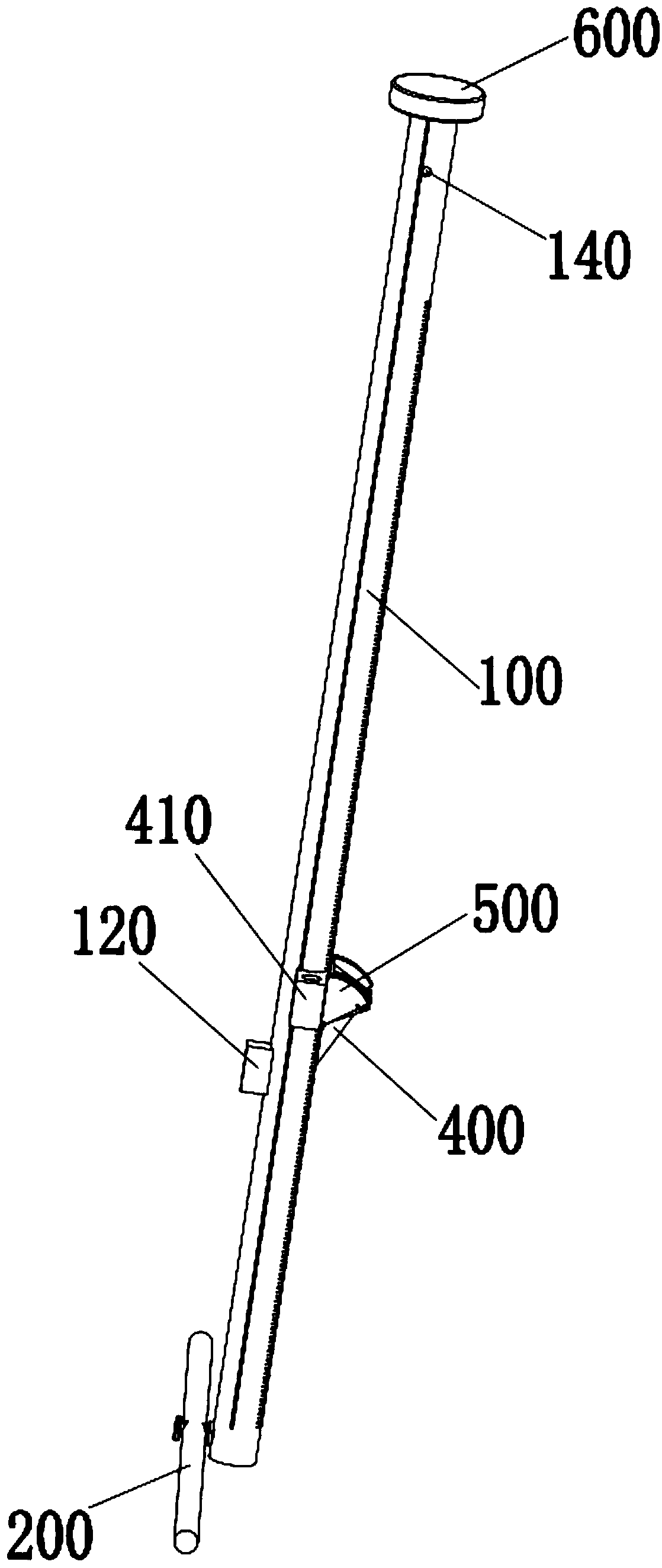
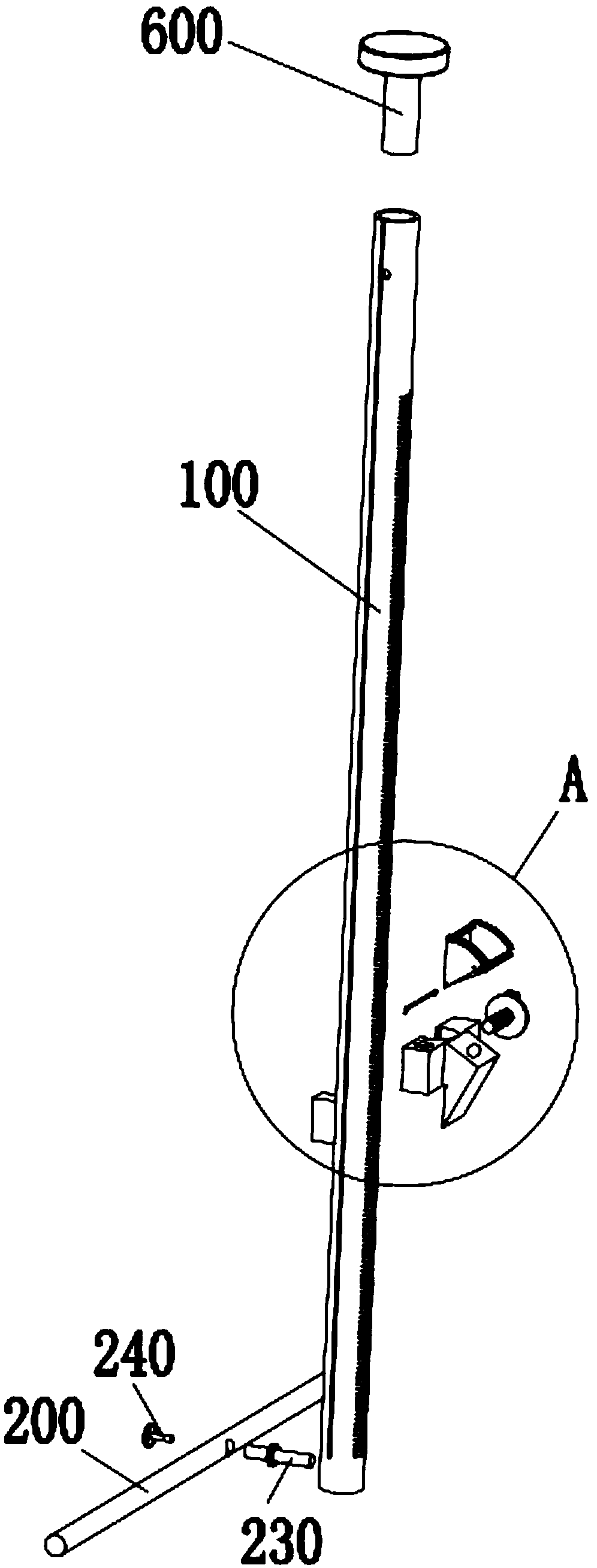
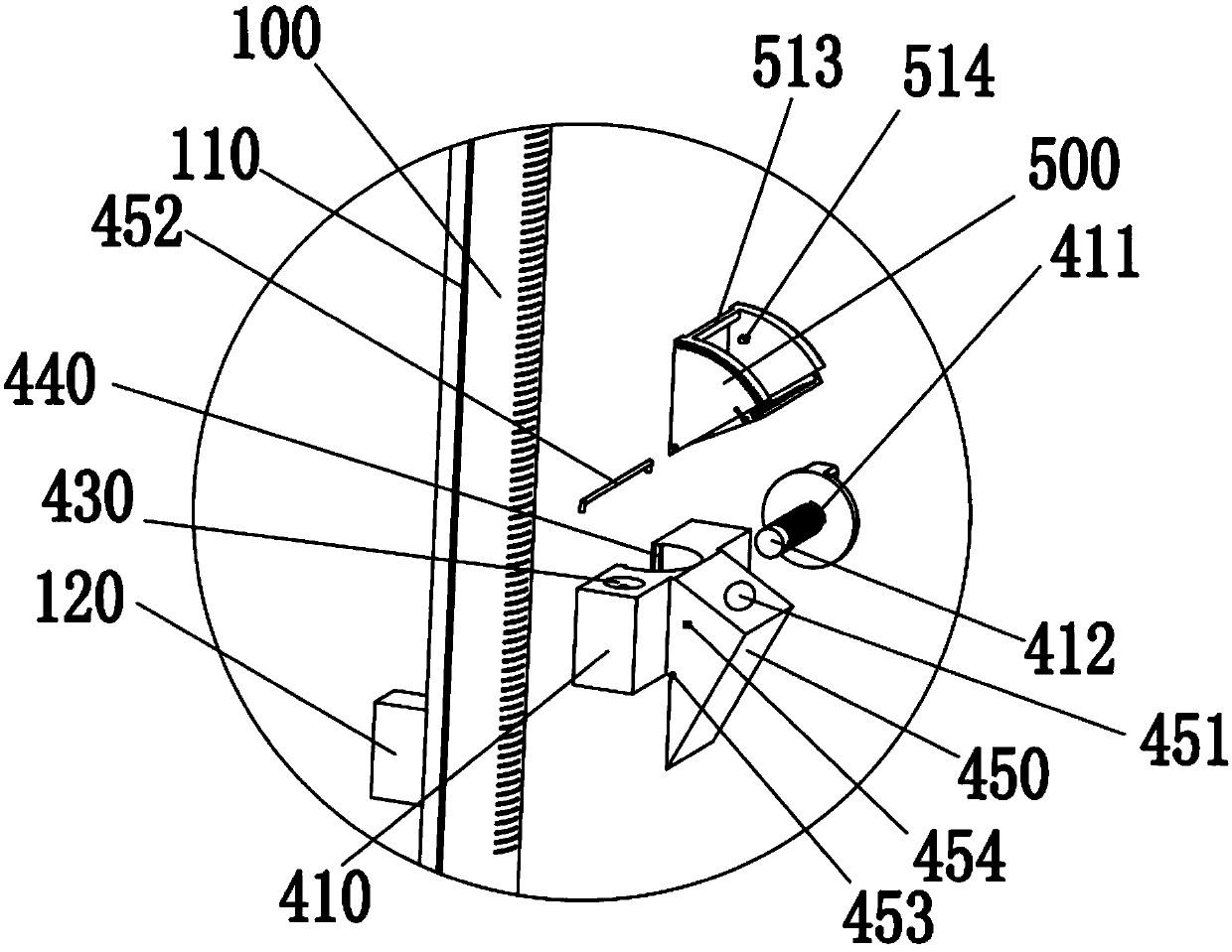
[0045] Such as Figure 1-Figure 14 As shown, a simple measuring device for accurately measuring the thickness of floor slabs includes a vertical rod 100 with a scale mark and a rotating rod 200 for blocking the bottom of the floor 300. The rotating rod 200 is hinged at the bottom end of the vertical rod 100. When When the rotating rod 200 is connected to the bottom of the floor 300, the horizontal plane of the connection is aligned with the zero scale on the vertical rod 100, including the sliding rule 400, which is socketed outside the vertical rod 100 and can reciprocate along the vertical rod 100 Movement, the two sides of the sliding rule 400 have a blocking part 410 that blocks the surface of the floor 300, and the sliding rule 400 has a viewing window 420 for viewing the scale reading of the vertical rod 100, and the top surface of the blocking part 410 is perpendicular to the vertical rod 100 Moreover, a first universal spirit level 430 for measuring the horizontal dire...


PUM

PropertyMeasurementUnit
Angleaaaaaaaaaa

Abstract

The invention relates to a measuring device, in particular to a simple measuring device that can accurately measure the thickness of a floor slab, can be accommodated, and can be automatically and easily retracted. The rod is hinged at the bottom of the vertical rod. When the rotating rod is in contact with the bottom of the floor slab, the horizontal plane of its contact is aligned with the zero scale on the vertical rod, including a sliding rule, which is sleeved outside the vertical rod and can be moved along the vertical rod. The rod reciprocates, and an angle meter is set on the slide rule. The vertical rod cooperates with the universal level on the angle meter to measure holes with a large hole slope, which makes the measuring instrument more practical. A mirror with a magnifying glass is installed on the slide rule. Barrel, which greatly facilitates reading; a magnet is ingeniously arranged between the vertical bar and the horizontal bar, which can easily keep the measuring instrument vertical after the measurement is completed, so that the instrument can be taken from the hole, which shortens the measurement time; due to the frequency of use of the measuring instrument The reason for the low height is that the present invention has a storage function designed to prevent damage to a large extent.

Description

technical field [0001] The invention relates to a measuring device, in particular to a simple measuring device which can accurately measure the thickness of floor slabs, can be accommodated, and can be automatically and easily retracted. Background technique [0002] In the construction inspection and acceptance process of construction projects, in order to ensure that the thickness of the floor slab meets the design and specification requirements, it is necessary to measure the thickness of the floor slab. [0003] Generally, there are two methods for measuring plate thickness: one is an electronic instrument that uses the combination of electromagnetic wave kinematics and dynamics. When using it, two people are needed, one is upstairs, and the other is downstairs. Standing against the transmitter, the people upstairs have to use communication and mine-sweeping methods to make the receiver and transmitter in the same center to measure. Obviously, the efficiency is not high....

Claims


Application Information

Patent Timeline
IPC IPC(8): G01B5/06
CPCG01B5/06
Inventor 林东海叶盛周施施
Owner 陈雪美
Why Eureka
Try Eureka