VR (Virtual Reality) head-mounted display device and display method thereof

A display device and display method technology, which is applied in optics, instruments, nonlinear optics, etc., can solve problems such as human eye fatigue and digital image processing performance bottlenecks, and achieve the effect of reducing the burden on the retina of the human eye and relieving visual fatigue of the human eye

Active Publication Date: 2018-04-20
BOE TECH GRP CO LTD +1
View PDF24 Cites 9 Cited by
  • Summary
  • Abstract
  • Description
  • Claims
  • Application Information

AI Technical Summary

Problems solved by technology

The screen of the VR head-mounted display device is at a fixed spatial distance (usually the display screen is set at a distance of 25cm from the human eye), and the displayed image can always be clearly imaged on the retina of the human eye after passing through the fixed focal length lens. Because the pictures of the surrounding environment are at different spatial distances, according to the convex lens characteristics of the lens, only a specific spatial distance can be clearly imaged at the same time, while images at other spatial distances become blurred images in the human eye, that is, only for the human eye. The focused part has a clear image, while the other part is a blurred image. By comparison, it can be seen that the display screen of the VR head-mounted display device gives the human eye a larger clear image, so that the display screen of the VR head-mounted display device has more information for the human eye. In the imaging environment with high information content for a long time, it is easy to cause eye fatigue
[0004] In the prior art, the way to solve the above problem is to simulate the image with blurred depth of field through image processing, that is, to use CPU / GPU to render the image in real time to complete the blurred depth of field, but for the high refresh rate of the display screen of the VR head-mounted display device Due to the high image resolution requirements, the performance of digital image processing encounters a huge bottleneck, which cannot solve this problem well.

Method used


Image

  • VR (Virtual Reality) head-mounted display device and display method thereof
  • VR (Virtual Reality) head-mounted display device and display method thereof
  • VR (Virtual Reality) head-mounted display device and display method thereof

Examples


Embodiment Construction

[0030] In order to illustrate the present invention more clearly, the present invention will be further described below with reference to the preferred embodiments and accompanying drawings. Similar parts in the figures are denoted by the same reference numerals. Those skilled in the art should understand that the content specifically described below is illustrative rather than restrictive, and should not limit the protection scope of the present invention.

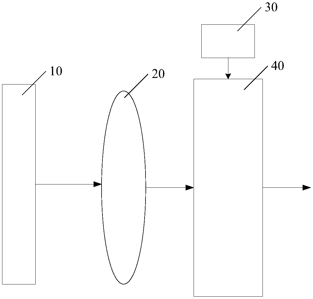
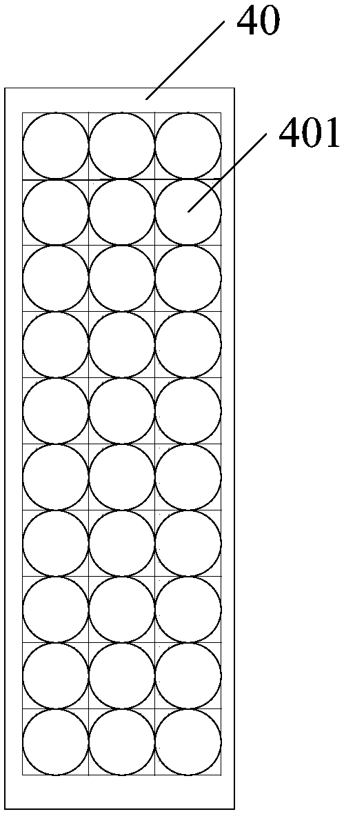
[0031] like figure 1 and figure 2 As shown together, an embodiment of the present invention provides a VR head-mounted display device, which includes a display screen 10 and a fixed focal length lens 20, and also includes a control unit 30 and a liquid crystal structure composed of a plurality of liquid crystal microlenses 401 arranged in an array. Microlens array 40, liquid crystal microlens array 40 such as figure 2 As shown, the control unit 30 applies a control voltage to the liquid crystal microlenses 401 at som...


PUM


Abstract

The invention discloses a VR (Virtual Reality) head-mounted display device and a display method thereof. The VR head-mounted display device comprises a display screen and a universal focus lens, and also comprises a control unit and a liquid crystal microlens array, wherein the liquid crystal microlens array is formed by multiple liquid crystal microlenses which are arrayed in an array manner; thecontrol unit applies control voltages to the liquid crystal microlens at partial positions in the liquid crystal microlens array, so that a focal point of light emitted by a pixel at a correspondingposition of the display screen and transmitting the liquid crystal microlens at the partial positions is deviated from a retina of a human eye. The VR head-mounted display device can be used for lightening load of the retina of the human eye through enabling a partial image viewed by the human eye to become fuzzy, and further, the visual fatigue of the human eye is relieved.

Description

technical field [0001] The invention relates to the field of display technology. More specifically, it relates to a VR head-mounted display device and a display method thereof. Background technique [0002] At present, with the advancement of VR (Virtual Reality) technology, VR head-mounted display devices are becoming more and more popular, and higher and higher requirements are put forward for the user experience performance of the head-mounted display devices. Current head-mounted display devices usually include a display screen, a fixed-focus lens and a head-mounted component. When using the user, the head-mounted component is fixed on the head so that the display screen is kept in front of the face, and the light emitted by the display screen passes through the fixed-focus lens. After focusing on the retina of the human eye, the image displayed on the display screen is clearly imaged on the retina of the human eye. [0003] One of the problems that the existing VR hea...

Claims


Application Information

Patent Timeline
Patent Type & Authority Applications(China)
IPC IPC(8): G02B27/01G02F1/29
CPCG02B27/0101G02B27/0172G02B2027/014G02F1/29
Inventor 方浩博白璐华刚米磊王景棚包智颖林坚薛艳娜张勇
Owner BOE TECH GRP CO LTD
Why Eureka
Try Eureka