Rainproof system of transformer

A transformer and transformer box technology, which is applied in the direction of transformer/inductor cooling, transformer/inductor casing, transformer/inductor parts, etc., can solve the problems of complex structure of automatic rain shielding device, increased transportation cost, and large space occupation , to facilitate transportation, reduce transportation costs, and reduce occupied space

Inactive Publication Date: 2018-04-20
YANCHENG POWER SUPPLY CO STATE GRID JIANGSU ELECTRIC POWER CO +4
View PDF1 Cites 2 Cited by
  • Summary
  • Abstract
  • Description
  • Claims
  • Application Information

AI Technical Summary

Problems solved by technology

[0005] The above-mentioned transformer rainproof device not only has a good rainproof function, but also has a good heat dissipation effect, which ensures the normal operation of the transformer and prolongs the service life of the transformer; however, there are still certain defects in the transformer rainproof device of this structure: The structure of the automatic rain shielding device in the structure is relatively complicated, and the automatic rain shielding device can only be used in rainy weather
In order to simplify the rainproof device, people directly connect a rain shelter to the upper end of the transformer box. The improvement of this structure simplifies the rainproof device, but because it is fixedly connected with the transformer box, the volume is relatively large, so In the process of transportation, it takes up a lot of space, so that the transportation volume is relatively reduced, thereby increasing the transportation cost

Method used


Image

  • Rainproof system of transformer
  • Rainproof system of transformer

Examples


Embodiment

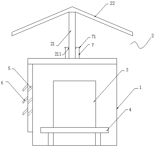
[0017] In this embodiment, the transformer rain-shielding system, such as figure 1 As shown, it includes a transformer box 1 and a rain shielding device 2, a base 4 for placing a transformer 3 with a preset height is arranged in the transformer box, and several strip-shaped cooling holes 5 are provided on the side wall of the transformer box 1 to dissipate heat. The hole 5 is an oblique through hole with a high inside and a low outside. A baffle plate 6 for keeping out the rain is arranged above the cooling hole 5 . The rain shielding device 2 is fixedly installed above the transformer box 1 .

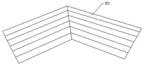
[0018] The rain shielding device 2 includes a connecting fixed rod 21 and a rain shelter 22 arranged on the upper end of the connecting fixed rod 21. The rain shelter 22 is an integrally formed inverted V-shaped rain shield, and the bottom of the rain shield is located in the transformer box. On both sides of the body, the inverted V-shaped structure of the rain shield can effectively ...


PUM


Abstract

The invention relates to a transformer rain-shielding system, which includes a transformer box and a rain-shielding device. The rain-shielding device includes a connecting fixed rod and a rain-shielding shed arranged on the upper end of the connecting and fixing rod. The rain-shielding shed is an integrally formed inverted The rain shield of V-shaped structure, and the bottom of the rain shield is located on both sides of the transformer box; a plug-in slot is provided in the center of the upper end face of the transformer box, and an outward-facing And the inner diameter of the protrusion A is larger than the inner diameter of the insertion groove, and the lower end surface of the connecting fixed rod is provided with a protrusion B cooperating with the protrusion A. The advantages of the present invention are: compared with the existing transformer rain-proof device, the rain-shielding device is greatly simplified, so that the overall structure is simple, and the rain-shielding device and the transformer box are fixedly connected by bolts, which is convenient for installation; at the same time, during transportation In the middle, the rain shielding device and the transformer box can be disassembled, and then during the installation and transportation, the occupied space can be reduced, the transportation is convenient, and the transportation cost can also be greatly reduced.

Description

technical field [0001] The invention relates to the technical field of power systems, in particular to a transformer rain shielding system. Background technique [0002] In our power system, various high and low voltage transformers are very important and frequently used power equipment, and most of the transformers are usually installed outdoors to facilitate ventilation and maintenance. However, this kind of transformer placed outdoors also has this big disadvantage. It is easy to be exposed to rain and snow. Due to the long-term rainwater immersion, it is easy to cause short circuit of the internal circuit and moisture inside the oil tank. Therefore, the transformer is usually placed in the transformer. in the box. [0003] Moreover, if the transformer needs to be repaired in rainy days, the box needs to be opened. After the box is opened, the rain cannot be effectively blocked. If the maintenance personnel do not use an umbrella, the rain will enter the transformer from...

Claims


Application Information

Patent Timeline
IPC IPC(8): H01F27/02H01F27/08H01F27/00H02B1/28
CPCH01F27/02H01F27/00H01F27/025H02B1/28
Inventor 袁航杨兵张伟峰汤国庆
Owner YANCHENG POWER SUPPLY CO STATE GRID JIANGSU ELECTRIC POWER CO
Why Eureka
Try Eureka