

Riveting machine
A technology of riveting press and pressing mechanism, applied in electrical components, circuits, connections, etc., can solve problems such as waste of human resources and low work efficiency, and achieve the effect of improving product qualification rate, improving work efficiency, and saving human resources.
- Summary
- Abstract
- Description
- Claims
- Application Information
AI Technical Summary
Problems solved by technology
Method used
Image

Examples
Embodiment Construction
[0045] The present invention will be described in further detail below in conjunction with the accompanying drawings.
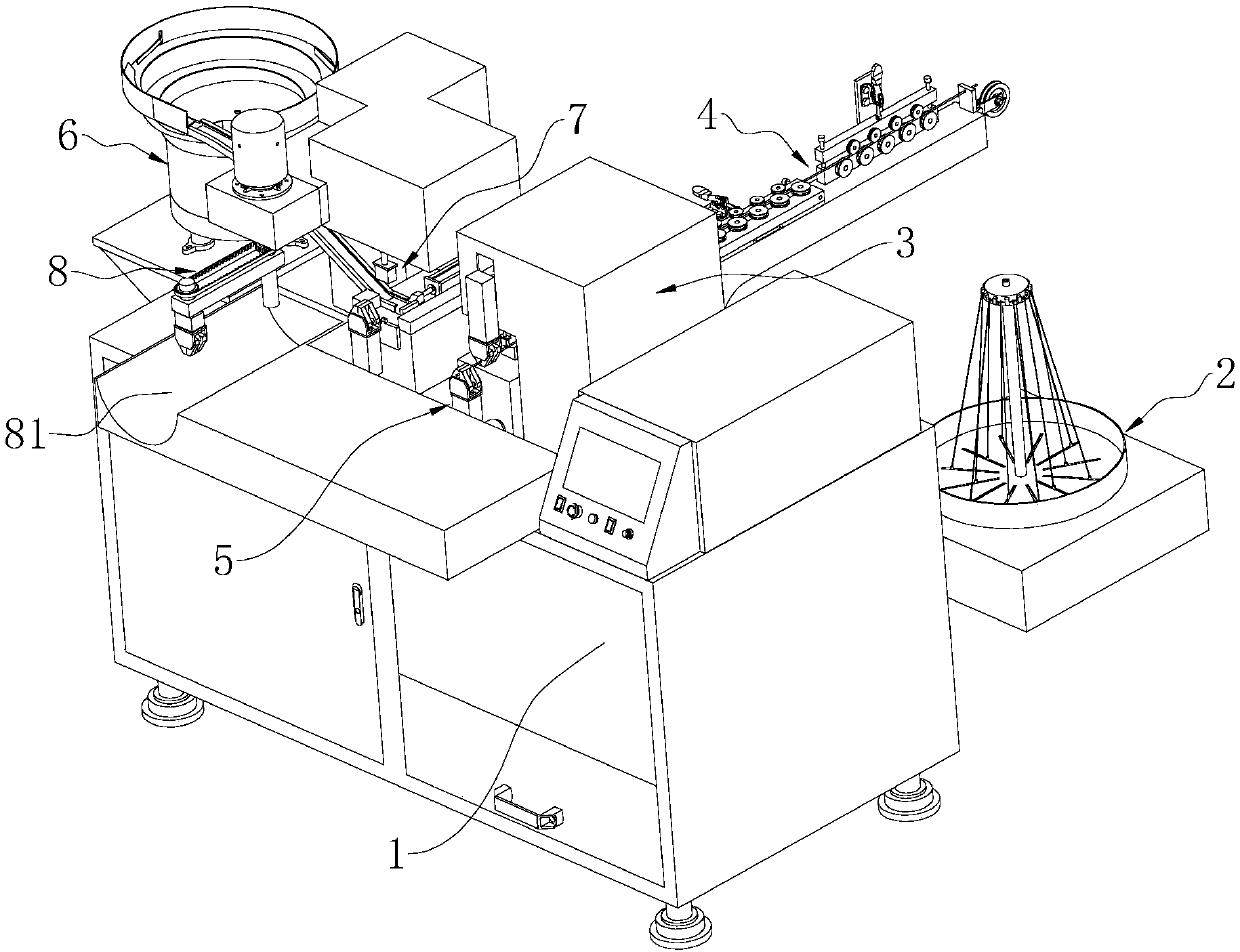
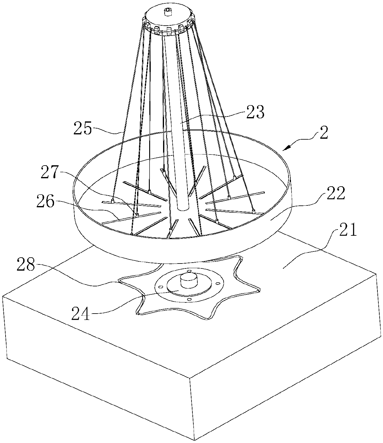
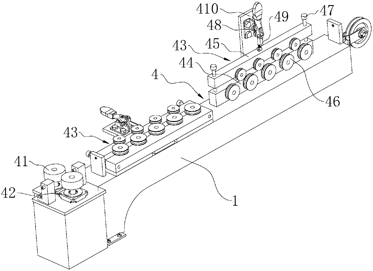
[0046] A riveting press, such as figure 1 As shown, it includes a frame 1, and the frame 1 is sequentially provided with a wire releasing mechanism 2, a first conveying mechanism 4, a wire stripping mechanism 3, a second conveying mechanism 5, a pressing mechanism 7, a third conveying mechanism 6 and a wire take-up mechanism. Mechanism 8, the coiled wires are placed in the pay-off mechanism 2 and conveyed to the stripping mechanism 3 by the first conveying mechanism 4, the second conveying mechanism 5 conveys the stripped wires to the pressing mechanism 7, and the terminals pass through the first The third conveying mechanism 6 is transported to the pressing mechanism 7 to be connected with the electric wire, and then the electric wire and the terminal are punched through the pressing mechanism 7, and the terminal is fixed on the electric wire, and finally th...
PUM
 Abstract
Description
Claims
Application Information