A topology of mmc modules applied to flexible direct current transmission systems
A technology of power transmission system and topology structure, applied in the field of MMC module topology structure, can solve the problems of loss, topology structure cannot effectively block DC faults, etc., and achieve the effect of suppressing fault current
- Summary
- Abstract
- Description
- Claims
- Application Information
AI Technical Summary
Problems solved by technology
Method used
Image
Examples
Embodiment 1
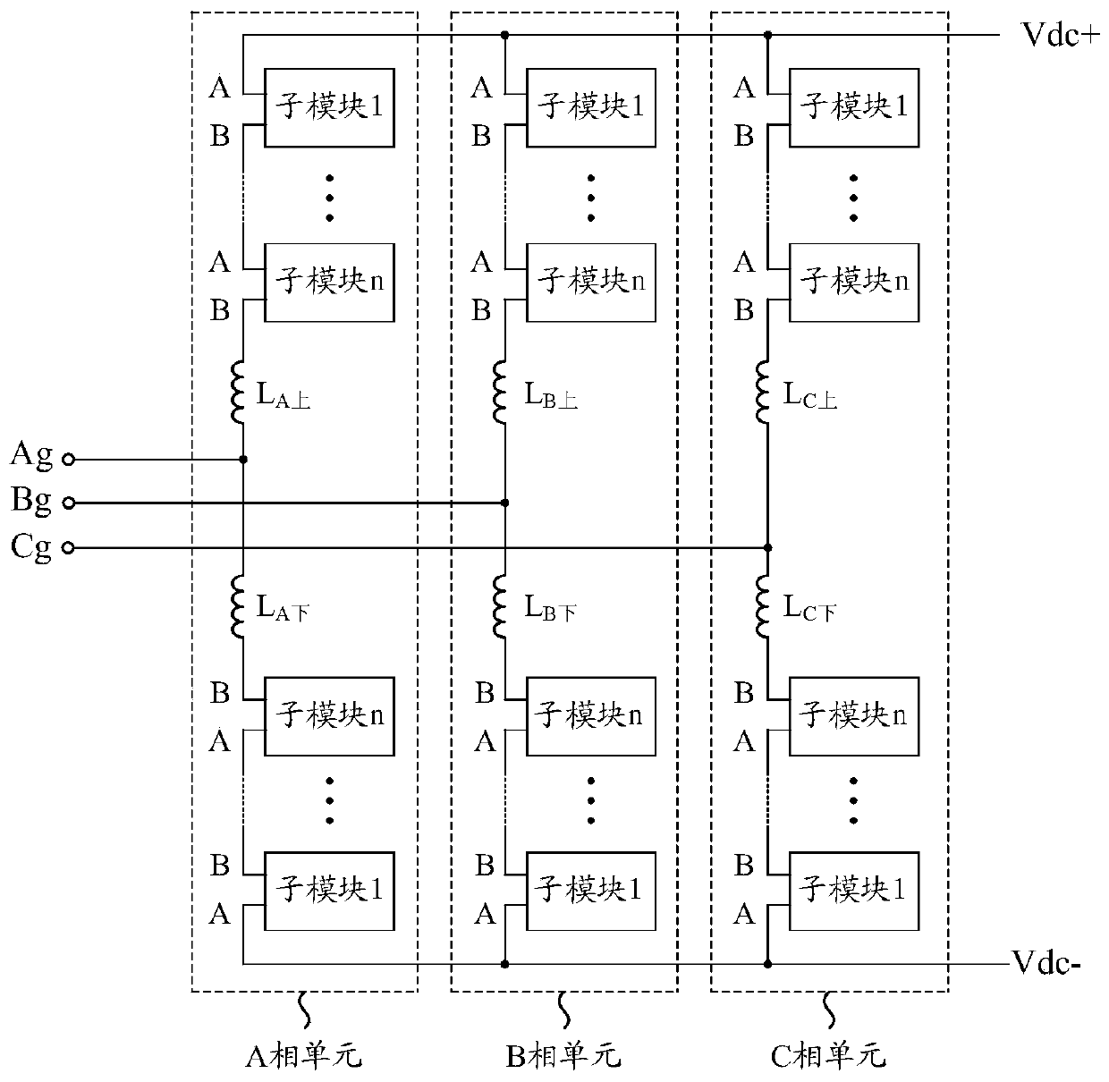
[0023] Such as figure 1 As shown, this embodiment provides a MMC (ModularMultilevel Converter, Modular Multilevel Converter) module topology applied to a flexible direct current transmission system, which includes three phase units, namely A phase unit and B phase unit As for the C-phase unit, each phase unit includes an upper bridge arm and a lower bridge arm. The upper bridge arm and the lower bridge arm of each phase unit have the same structure, and both include reactors L and n sub-modules connected in series in sequence. The number of sub-modules in each phase unit is determined by factors such as the DC bus voltage, the withstand voltage level of electronic devices, and the type of sub-modules at the beginning of the system design. In this embodiment, the number of sub-modules of each phase unit m=2n=Udc / U SM , where Udc is the voltage between the positive and negative DC bus, U SM is the capacitor voltage of each sub-module, n is the number of sub-modules on each bri...
Embodiment 2
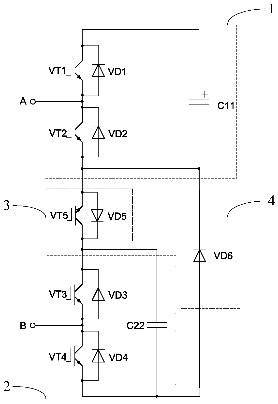
[0041] Such as figure 2 As shown, this embodiment provides a sub-module. In the first unit 1 of the sub-module, the collector of the transistor VT1 is respectively connected to the cathode of the diode VD1 and the anode of the capacitor C11, and the emitter of the transistor VT1 is respectively connected to the diode VD1. The positive pole is connected to the collector of the transistor VT2, the collector of the transistor VT2 is also connected to the negative pole of the diode VD2, the emitter of the transistor VT2 is respectively connected to the positive pole of the diode VD2, and the negative pole of the capacitor C11, and the output terminal A is connected to the emitter of the transistor VT1 and The connection points of the collectors of the transistor VT2 are connected;
[0042] In the second unit 2 of the sub-module, the collector of the transistor VT3 is respectively connected to the cathode of the diode VD3 and the anode of the capacitor C22, the emitter of the tran...
Embodiment 3
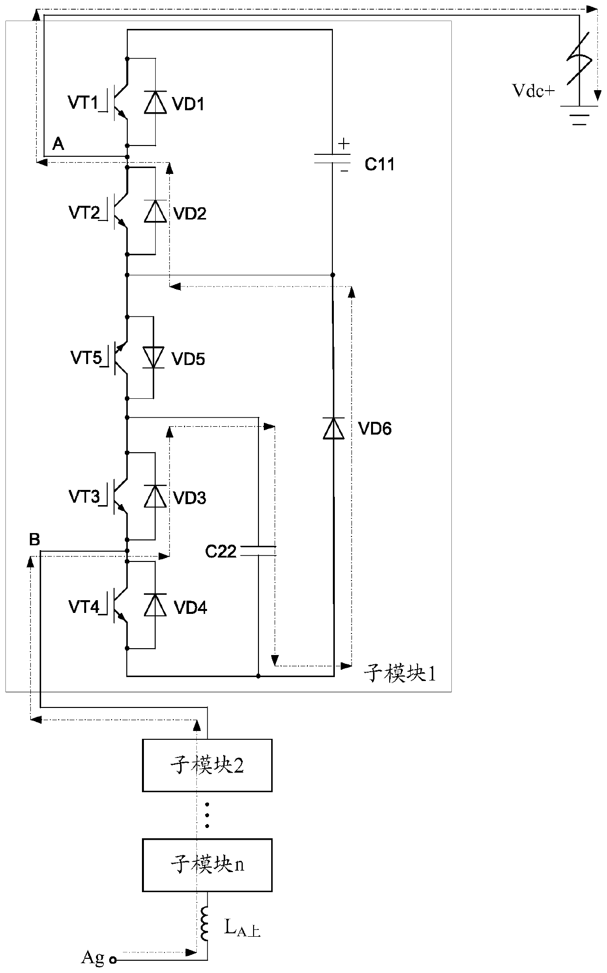
[0083] Such as Figure 5 As shown, this embodiment provides a sub-module. In the first unit 1 of the sub-module, the collector of the transistor VT1 is respectively connected to the cathode of the diode VD1 and the anode of the capacitor C11, and the emitter of the transistor VT1 is respectively connected to the diode VD1. The positive pole is connected to the collector of the transistor VT2, the collector of the transistor VT2 is also connected to the negative pole of the diode VD2, the emitter of the transistor VT2 is respectively connected to the positive pole of the diode VD2, and the negative pole of the capacitor C11, and the output terminal A is connected to the emitter of the transistor VT1 and The connection points of the collectors of the transistor VT2 are connected;
[0084] In the second unit 2 of the sub-module, the collector of the transistor VT3 is respectively connected to the cathode of the diode VD3 and the anode of the capacitor C22, the emitter of the tran...
PUM
 Abstract
Description
Claims
Application Information
 - R&D
- Intellectual Property
- Life Sciences
- Materials
- Tech Scout
- Unparalleled Data Quality
- Higher Quality Content
- 60% Fewer Hallucinations
Browse by: Latest US Patents, China's latest patents, Technical Efficacy Thesaurus, Application Domain, Technology Topic, Popular Technical Reports.
© 2025 PatSnap. All rights reserved.Legal|Privacy policy|Modern Slavery Act Transparency Statement|Sitemap|About US| Contact US: help@patsnap.com


