Plant raw material shredding device for new energy biogas digester

A plant raw material and biogas digester technology, which is applied in the field of plant raw material cutting equipment for new energy biogas digesters, can solve the problems of cumbersome operation, long time required, poor cutting effect, etc., and achieves the effect of promoting a stable process

Active Publication Date: 2018-04-24
JINYIMENG GRP CO LTD
View PDF13 Cites 8 Cited by
  • Summary
  • Abstract
  • Description
  • Claims
  • Application Information

AI Technical Summary

Problems solved by technology

[0005] In order to overcome the disadvantages of poor cutting effect, long time required and cumbersome operation of the traditional shredding mechanism, the technical problem to be solved by the present invention is to provide a new energy biogas with good cutting effect, short time consumption and easy operation. Pond plant material chopping equipment

Method used


Image

  • Plant raw material shredding device for new energy biogas digester
  • Plant raw material shredding device for new energy biogas digester

Examples


Embodiment 1

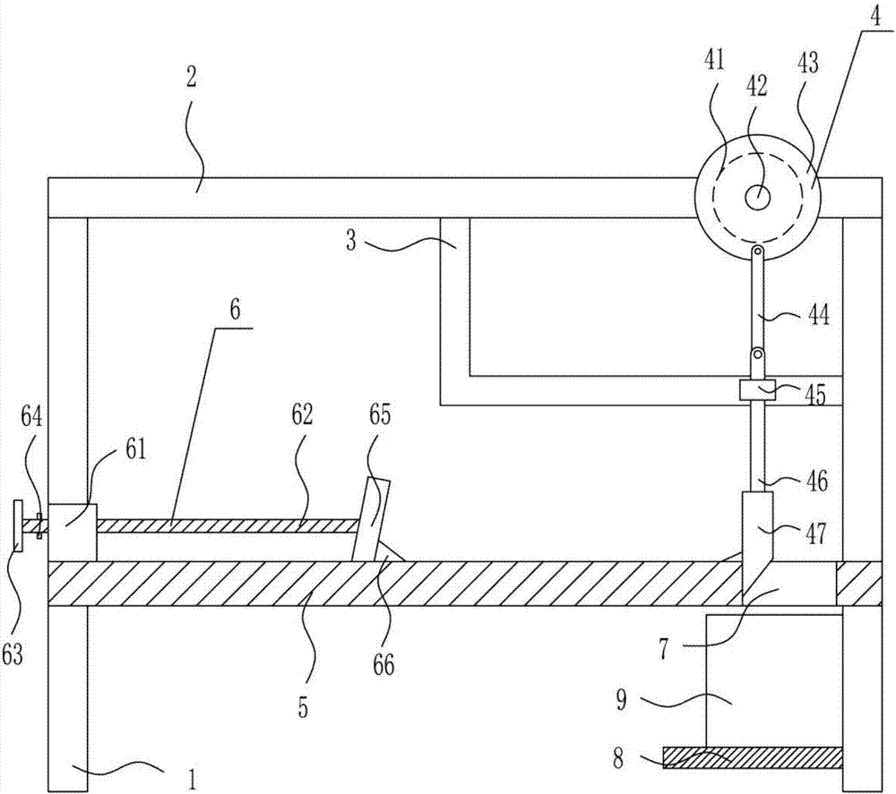
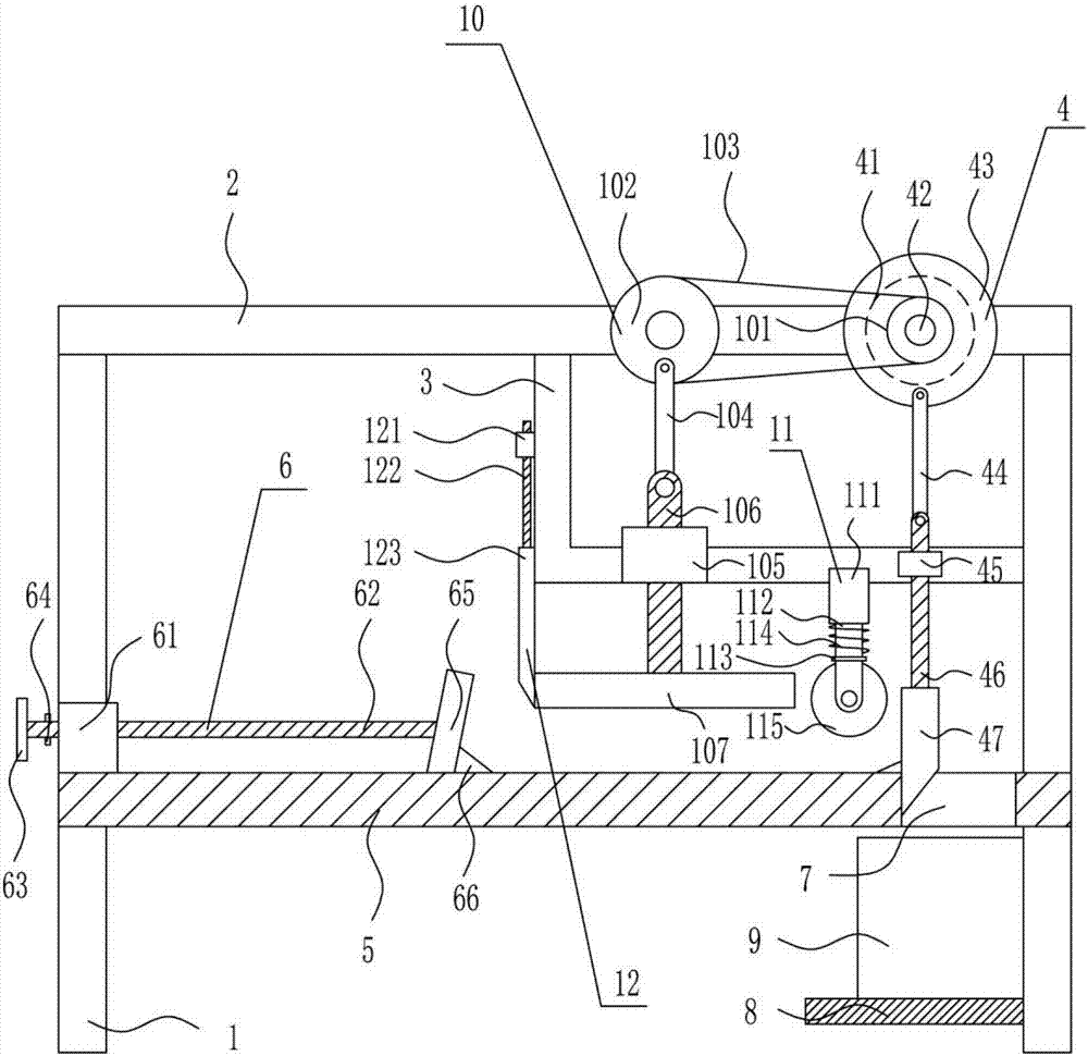
[0026] A plant raw material chopping equipment for new energy biogas digesters, such as Figure 1-2 As shown, it includes a support leg 1, a support plate 2, an L-shaped rod 3, a cutting mechanism 4, a mounting plate 5, a pushing mechanism 6, a placement plate 8 and a collection box 9, and the top of the left and right legs 1 is provided with a support plate 2 , an L-shaped rod 3 is connected between the bottom of the support plate 2 and the inner wall of the right leg 1, a cutting mechanism 4 is installed on the support plate 2, and a mounting plate 5 is connected to the middle of the inner wall of the left and right leg 1, and the mounting plate 5 is equipped with a push mechanism 6, the right side of the mounting plate 5 has a through hole 7, the bottom of the inner wall of the right leg 1 is horizontally connected with a placement plate 8, and a collection box 9 is placed on the placement plate 8, and the through hole 7 is located Directly above collection box 9.

Embodiment 2

[0028] A plant raw material chopping equipment for new energy biogas digesters, such as Figure 1-2 As shown, it includes a support leg 1, a support plate 2, an L-shaped rod 3, a cutting mechanism 4, a mounting plate 5, a pushing mechanism 6, a placement plate 8 and a collection box 9, and the top of the left and right legs 1 is provided with a support plate 2 , an L-shaped rod 3 is connected between the bottom of the support plate 2 and the inner wall of the right leg 1, a cutting mechanism 4 is installed on the support plate 2, and a mounting plate 5 is connected to the middle of the inner wall of the left and right leg 1, and the mounting plate 5 is equipped with a push mechanism 6, the right side of the mounting plate 5 has a through hole 7, the bottom of the inner wall of the right leg 1 is horizontally connected with a placement plate 8, and a collection box 9 is placed on the placement plate 8, and the through hole 7 is located Directly above collection box 9.

[0029]...

Embodiment 3

[0031] A plant raw material chopping equipment for new energy biogas digesters, such as Figure 1-2 As shown, it includes a support leg 1, a support plate 2, an L-shaped rod 3, a cutting mechanism 4, a mounting plate 5, a pushing mechanism 6, a placement plate 8 and a collection box 9, and the top of the left and right legs 1 is provided with a support plate 2 , an L-shaped rod 3 is connected between the bottom of the support plate 2 and the inner wall of the right leg 1, a cutting mechanism 4 is installed on the support plate 2, and a mounting plate 5 is connected to the middle of the inner wall of the left and right leg 1, and the mounting plate 5 is equipped with a push mechanism 6, the right side of the mounting plate 5 has a through hole 7, the bottom of the inner wall of the right leg 1 is horizontally connected with a placement plate 8, and a collection box 9 is placed on the placement plate 8, and the through hole 7 is located Directly above collection box 9.

[0032]...


PUM


Abstract

The invention relates to a new energy material processing device, in particular to a plant raw material shredding device for a new energy biogas digester. According to the plant raw material shreddingdevice for the new energy biogas digester, the cutting effect is good, the used time is short, and operation is easy and convenient. The plant raw material shredding device for the new energy biogasdigester comprises supporting legs and the like. A supporting plate is arranged at the tops of the supporting legs of the left side and the right side, and an L-shaped rod is connected between the bottom of the supporting plate and the inner side wall of the supporting leg of the right side. A cutting mechanism is mounted on the supporting plate, and a mounting plate is connected to the middles ofthe inner side walls of the supporting legs of the left side and the right side. A pushing mechanism is mounted on the mounting plate. According to the plant raw material shredding device, through mutual cooperation of the cutting mechanism and the pushing mechanism, raw materials are sufficiently cut, meanwhile the cut raw materials are collected through a collecting box, and through optimization of a compressing mechanism, an auxiliary mechanism and a protective mechanism, the good cutting effect is achieved.

Description

technical field [0001] The invention relates to a new energy raw material processing equipment, in particular to a plant raw material chopping equipment for a new energy biogas digester. Background technique [0002] New energy: also known as unconventional energy. Refers to various forms of energy other than traditional energy. Refers to energy sources that have just begun to be developed and utilized or are being actively researched and yet to be promoted, such as solar energy, geothermal energy, wind energy, ocean energy, biomass energy, and nuclear fusion energy. [0003] When using plant raw materials to ferment materials in biogas digesters, the raw materials need to be shredded to ensure high gas production efficiency. The traditional shredding mechanism has poor cutting effect, takes a long time, and is cumbersome to operate. Therefore, it is urgent It is necessary to develop a plant raw material cutting equipment for new energy biogas digesters with good cutting e...

Claims


Application Information

Patent Timeline
Patent Type & Authority Applications(China)
IPC IPC(8): B02C18/02B02C18/04B02C23/04B30B9/30B30B3/00
CPCB02C18/02B02C18/04B02C23/04B30B3/00B30B9/30
Inventor 王臻任益昌吕苗苗
Owner JINYIMENG GRP CO LTD
Why Eureka
Try Eureka