
Powder metallurgy fan-shaped piece compound punching die

A powder metallurgy and fan-shaped piece technology, which is applied in the field of powder metallurgy re-punching dies, can solve the problems of inconvenient maintenance and repair, poor running stability, and low punching quality, so as to achieve stable and smooth feeding, not easy to interrupt, and stable and reliable operation Effect

Active Publication Date: 2018-04-24
CRRC YONGJI ELECTRIC CO LTD
View PDF6 Cites 1 Cited by
  • Summary
  • Abstract
  • Description
  • Claims
  • Application Information

AI Technical Summary

Problems solved by technology

[0003] The invention solves the problems of unreasonable structure, poor operation stability, low punching quality, short die life and inconvenient maintenance and repair of existing powder metallurgy fan-shaped re-punching dies, and provides a punching die with reasonable structure, stable operation and high punching quality. Good, long mold life, convenient maintenance of powder metallurgy segment re-punching die

Method used


Image

  • Powder metallurgy fan-shaped piece compound punching die
  • Powder metallurgy fan-shaped piece compound punching die
  • Powder metallurgy fan-shaped piece compound punching die

Examples


Embodiment Construction

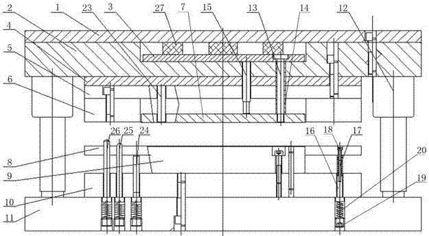
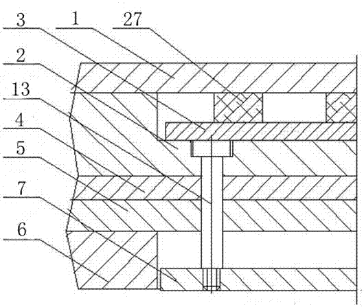
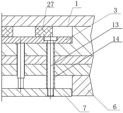
[0014]The powder metallurgy fan-shaped piece compound punching die includes a compound punching die body, and the compound punching die body includes an upper die cover plate 1, an upper die seat 2, a punching plate 3, an upper backing plate 4, an upper fixing plate 5, a die 6, and a push plate 7 , unloading plate 8, punch 9, lower fixing plate 10, lower mold base 11, ball guide post 12, the upper surface of said beating plate 3 has a countersunk through hole, and the bottom of the beating cavity of said upper die base 2 , the upper backing plate 4 and the upper fixing plate 5 are provided with punching bolt holes corresponding to the through holes of the countersunk head, and the punching bolts whose lower ends are screwed on the push plate 7 are provided in the through holes of the countersunk head and the punching bolt holes. The material bolt 13 is covered with a material contour cover 14, the upper end of the material contour cover 14 is supported on the lower surface of t...


PUM


Abstract

The invention relates to a powder metallurgy compound punching die, in particular to a powder metallurgy fan-shaped piece compound punching die. The powder metallurgy fan-shaped piece compound punching die solves the problems that an existing powder metallurgy fan-shaped piece compound punching die is unreasonable in structure, poor in operation stability, not high in punching quality is, short indie life and inconvenient to maintain and repair. According to the scheme, the powder metallurgy fan-shaped piece compound punching die comprises an upper die cover plate, an upper die seat, a smashing plate, an upper cushion plate, an upper fixed plate, a female die, a pushing plate, an unloading plate, a male die, a lower fixed plate, a lower die seat, a material smashing bolt, a material smashing equal-height sleeve, a smashing rod, an unloading bolt, an unloading equal-height sleeve, a rectangular splicing block and a punching head. The powder metallurgy fan-shaped piece compound punchingdie has the advantages that 1, the depth of parallelism of the pushing plate and the smashing plate is ensured through the material smashing equal-height sleeve, material smashing is steady and smooth, material jamming does not occur, and the material smashing bolt is not prone to breaking; 2, the protruding height of the unloading plate is ensured through the unloading equal-height sleeve, adjusting of unloading elastic force is convenient, and the life of the spring is long; 3, male die comb teeth are firm and do not shake; and 4, a splicing joint of the rectangular splicing block is reasonable, deformation is small, the punching head of a female die comb tooth part is connected firmly, gap grinding is convenient, and a punching piece has the high quality.

Description

technical field [0001] The invention relates to a powder metallurgy compound punching die, in particular to a powder metallurgy segment compound punching die. Background technique [0002] Powder metallurgy has been widely used in single-slot dies in die manufacturing, and the punching life can reach more than one million times. This material has the characteristics of extremely high wear resistance, high compressive strength, good hardenability, good toughness, good heat treatment stability, and very good tempering stability. For large-scale recoil dies, due to the difficulties in powder metallurgy in terms of module size, thickness, processing, and die structure, it is difficult to extend this technology to large-scale recoil dies. The existing large-scale re-punching dies are upper mold cover plate 1, upper mold base 2, beating plate 3, upper backing plate 4, upper fixing plate 5, die 6, push plate 7, unloading plate 8, from top to bottom. Convex die 9, lower fixed plat...

Claims


Application Information

Patent Timeline
Patent Type & Authority Applications(China)
IPC IPC(8): B21D28/14B21D37/01
Inventor 刘保平尚江波刘希锋张峰杰陈建军席震
Owner CRRC YONGJI ELECTRIC CO LTD
Learn More