Valve polishing device

A valve, No. 1 technology, applied in the field of valve grinding device, can solve the problems of reducing the efficiency of valve grinding, reducing the grinding efficiency, and easy deviation of valve position, so as to achieve the effect of reducing work intensity, improving grinding quality, and convenient and quick grinding

Inactive Publication Date: 2018-04-24
XINCHANG LIYONGDA REFRIGERATION MACHINERY
View PDF6 Cites 12 Cited by
  • Summary
  • Abstract
  • Description
  • Claims
  • Application Information

AI Technical Summary

Problems solved by technology

[0004] The purpose of the present invention is to provide a valve grinding device to solve the problem that the existing valve grinding device has a relatively simple structure when fixing the valve, and cannot fix the valve well during the grinding process, resulting in the valve being easily positioned during grinding. Offset, resulting in inaccurate grinding position, re-grinding is required, which reduces the grinding efficiency and affects the appearance quality of the valve, not only wastes working time, but also increases work costs, and slag and dust will appear during the grinding process The splash is not easy to clean, and the existing grinding device, the grinding disc cannot be moved and rotated, which affects the grinding quality of the valve and reduces the efficiency of the valve grinding

Method used


Image

  • Valve polishing device
  • Valve polishing device

Examples


Embodiment Construction

[0017] The following will clearly and completely describe the technical solutions in the embodiments of the present invention with reference to the accompanying drawings in the embodiments of the present invention. Obviously, the described embodiments are only some, not all, embodiments of the present invention. Based on the embodiments of the present invention, all other embodiments obtained by persons of ordinary skill in the art without making creative efforts belong to the protection scope of the present invention.

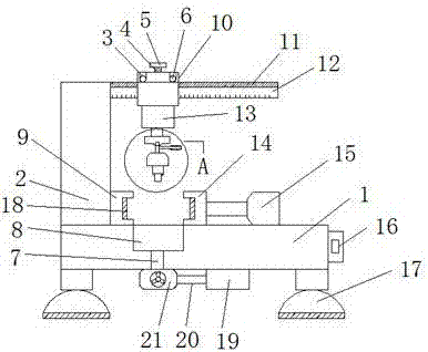
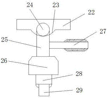
[0018] see Figure 1-2 , the present invention provides a technical solution: a valve grinding device, including a base 1, a column 2, a connecting rod 3, a screw 4, a turntable 5, a pulley 6, an air pipe 7, a collection tank 8, a No. 1 clamp 9, and a fixing frame 10. Chute 11, beam 12, No. 1 cylinder 13, No. 2 fixture 14, No. 2 cylinder 15, controller 16, support feet 17, anti-slip mat 18, dust storage box 19, dust exhaust pipe 20, vacuum cleaner 21, connecti...


PUM


Abstract

The invention discloses a valve polishing device. The valve polishing device comprises a base, a vertical column and a crossbeam. The vertical column is fixedly connected to the upper end of the base,and one side of the vertical column is fixedly connected with the crossbeam. The upper end of the base is fixedly connected with a first clamp, and a second clamp is arranged on one side of the firstclamp; the second clamp is slidably connected with the base; one side of the second clamp is fixedly connected with a second air cylinder; a collecting groove is formed in the surface of the base; adust collector is fixedly connected to the lower end of the base; a fixing frame is slidably connected to the outer side of the crossbeam; and the top of the fixing frame is rotatably connected with pulleys through connecting rods. According to the valve polishing device, the first clamp and the second clamp are arranged, the second clamp is fixedly connected with the second air cylinder, the second air cylinder pushes the second clamp to move, thus the distance between the first clamp and the second clamp can be effectively adjusted, and a valve can be well clamped, so that the valve is prevented from moving when being polished.

Description

technical field [0001] The invention relates to the technical field of valves, in particular to a valve polishing device. Background technique [0002] Valves are pipeline accessories used to open and close pipelines, control flow direction, adjust and control the parameters (temperature, pressure and flow) of the conveying medium. According to their functions, they can be divided into shut-off valves, check valves, regulating valves, etc. Valves are the control components in the fluid delivery system, with the functions of cut-off, regulation, flow diversion, reverse flow prevention, pressure stabilization, flow diversion or overflow pressure relief, etc. Valves used in fluid control systems range from the simplest cut-off valve to extremely complex The various valves used in the automatic control system have a wide variety of varieties and specifications. The valves can be used to control the flow of various types of fluids such as air, water, steam, various corrosive medi...

Claims


Application Information

Patent Timeline
Patent Type & Authority Applications(China)
IPC IPC(8): B24B19/00B24B41/06B24B55/06B24B55/12
CPCB24B19/00B24B41/06B24B55/06B24B55/12
Inventor 李永达
Owner XINCHANG LIYONGDA REFRIGERATION MACHINERY
Why Eureka
Try Eureka