
Kitchen oil separator tank with waste oil recycling function

A technology for grease traps and kitchens, applied in grease/oily substances/floating matter removal devices, liquid separation, separation methods, etc., can solve problems such as rapid water flow and unsatisfactory oil separation effect, and achieve the effect of recycling

Inactive Publication Date: 2018-04-24
DALIAN GAOMA ART DESIGN ENG
View PDF6 Cites 0 Cited by
  • Summary
  • Abstract
  • Description
  • Claims
  • Application Information

AI Technical Summary

Problems solved by technology

[0002] Most of the existing small grease traps on the market have evolved from the technical principles of large grease traps, using the different specific gravity of oil and water to separate oil and water, but there are differences between small grease traps and large ones It is due to the rapid water flow caused by the small space, so that the oil has been discharged before it is fully isolated, resulting in an unsatisfactory oil separation effect. This patent realizes the overall oil separation by adding slow flow plate components, changing the angle of the oil collection plate and other structural innovations. System-technical optimization of processes

Method used


Image

  • Kitchen oil separator tank with waste oil recycling function

Examples


Embodiment Construction

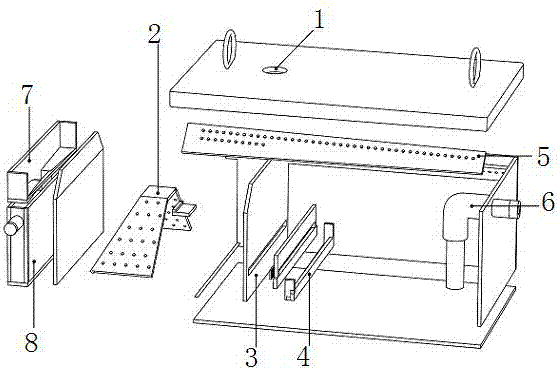
[0009] Such as figure 1 As shown, the kitchen grease trap that can recycle waste oil includes sewage inlet 1, slow flow baffle 2, partition 3, grille 4, oil collecting plate 5, outlet pipe 6, oil guide tank 7 and oil collecting box 8 , the slow flow baffle 2 is set at the lower part of the sewage inlet 1, the grille 4 is set at the bottom of the separator 3, the separator 3 is set at the bottom of the grease trap, the oil collecting plate 5 is set at the top of the grease trap, the outlet pipe 6 and the oil guide tank 7 are all arranged at the bottom of the grease trap, and the oil collection box 8 is arranged at the lower part of the oil guide tank 7. During operation, waste water enters the grease trap through the water inlet 1, and the speed of the water flow is slowed down by the slow flow baffle 2. After the water flow slows down , into the bottom of the primary grease trap, through the grille 4 at the bottom of the partition 3, into the secondary grease trap, the larger ...


PUM


Abstract

The invention discloses a kitchen oil separator tank with a waste oil recycling function, comprising a wastewater inlet, a slow flow baffle, a partition, a grille, an oil collecting plate, a water outflow pipe, an oil guide channel and an oil collecting box; the slow flow baffle is arranged below the wastewater inlet; the grille is arranged at the bottom of the partition that is arranged at the bottom of the tank; the oil collecting plate is arranged at the top of the tank; both the water outflow pipe and the oil guide channel are arranged at the bottom of the tank; the oil collecting box is arranged below the oil guide channel. The kitchen oil separator tank with the waste oil recycling function has the advantages that the slow flow baffle is used to retard water flows so that wastewaterslows at decreased speed after entering a primary separator tank, and oil dirt particles are crushed more finely; the angle of the oil collecting plate and arrangement of oil collecting holes in the oil collecting plate provide double filtering for oil dirt; therefore, oil separation effect of the separator tank is significantly better than separator tanks based on prior principles, and recyclingof waste oil is achieved.

Description

technical field [0001] The invention relates to a kitchen grease trap capable of recycling waste oil. Background technique [0002] Most of the existing small grease traps on the market have evolved from the technical principles of large grease traps, using the different specific gravity of oil and water to separate oil and water, but there are differences between small grease traps and large ones It is due to the rapid water flow caused by the small space, so that the oil has been discharged before it is fully isolated, resulting in an unsatisfactory oil separation effect. This patent realizes the overall oil separation by adding slow flow plate components, changing the angle of the oil collection plate and other structural innovations. System-technical optimization of processes. Contents of the invention [0003] The purpose of the present invention is to provide a kitchen grease trap which can recycle waste oil. [0004] The technical solution adopted by the present i...

Claims


Application Information

Patent Timeline
IPC IPC(8): C02F1/40
CPCC02F1/40
Inventor 司云飞秦永泽张明耀
Owner DALIAN GAOMA ART DESIGN ENG
Learn More