Composite multi-cylinder-linkage buffer and application thereof

A composite buffer technology, applied in the direction of shock absorbers, shock absorbers, springs/shock absorbers, etc., can solve problems such as unreliable and effective buffering, and achieve excellent effects, high buffering efficiency, and structural design reasonable effect

Active Publication Date: 2018-04-24
SHANDONG UNIV OF SCI & TECH
View PDF8 Cites 13 Cited by
  • Summary
  • Abstract
  • Description
  • Claims
  • Application Information

AI Technical Summary

Problems solved by technology

[0004] Under the working conditions of heavy load and heavy impact, the existing hydraulic buffers cannot reliably and effectively achieve buffering in some overloaded situations. How to reasonably set up and realize multi-stage joint buffering, so as to more effectively reduce the impact energy and impact Damage, a key component of the protective structure, is an issue that needs to be addressed in bumper design

Method used


Image

  • Composite multi-cylinder-linkage buffer and application thereof
  • Composite multi-cylinder-linkage buffer and application thereof
  • Composite multi-cylinder-linkage buffer and application thereof

Examples


Embodiment 1

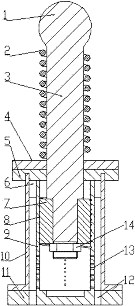
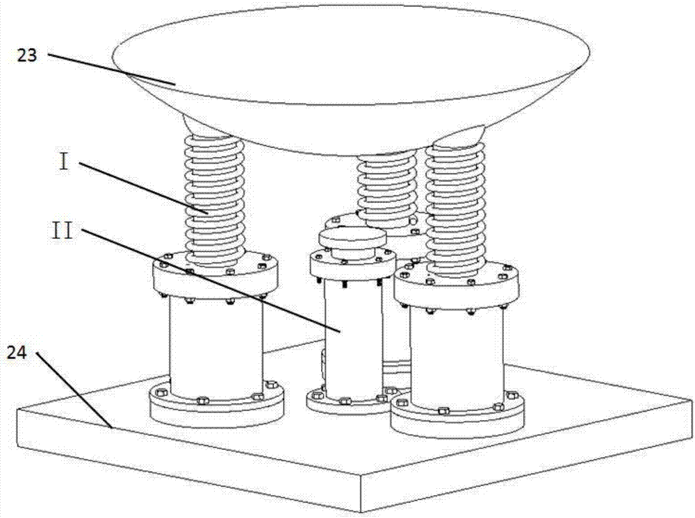
[0036] Such as Figure 1 to Figure 8 As shown, this embodiment provides a composite multi-cylinder linkage buffer, including a base plate 23 and a valve seat 24, and a liquid-pneumatic buffer II and three hydraulic buffers are arranged between the base plate 23 and the valve seat 24 Ⅰ. The bottom end of the hydraulic buffer is fixedly connected to the valve seat 24. The piston rod 3 of the hydraulic buffer is hinged to the bottom surface of the base plate 23. The bottom end of the hydraulic buffer is fixedly connected to the valve seat 24 and is connected to the hydraulic pressure Buffer connection; when the base plate 23 is impacted, multi-stage joint buffering is performed through the hydraulic buffer and the liquid-air buffer.

[0037] Wherein, the base plate 23 is a convex disc, the upper top surface of the convex disc is a circular plane, and the lower bottom surface is a hemispherical surface.

[0038] The hydraulic shock absorber includes an outer cylinder 10, a cylind...

Embodiment 2

[0043] A composite multi-cylinder linkage buffer, the structure of which is as described in Embodiment 1, the difference is that a pressure accumulating sponge 6 is arranged between the cylinder liner 9 and the outer cylinder 10 .

Embodiment 3

[0045] A method for using the composite multi-cylinder linkage buffer as described in Embodiment 2, the specific operation process is as follows:

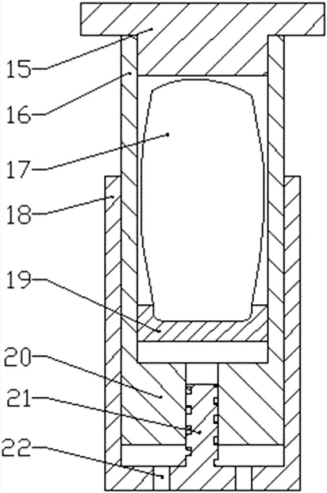
[0046] When the base plate 23 is impacted by foreign objects, the base plate 23 compresses the piston rod 3 of the hydraulic shock absorber downward, and the piston rod 3 shrinks so that the oil in the rodless cavity of the cylinder sleeve 9 enters through the spiral groove 8 and the orifice 13 respectively. There is a rod cavity and a valve seat 24 oil circuit. When the oil pressure in the valve seat 24 oil circuit is too high, the first safety valve 25 is opened, and the oil enters the cylinder 18 of the liquid-gas buffer, and the liquid-gas buffer The piston rod 16 protrudes upwards; when the piston 7 of the hydraulic buffer enters the area of ​​the orifice 13, the oil no longer enters the rod cavity, and the oil only enters through the orifice 13, the through hole 12, and the valve seat 24 Liquid-gas buffer until the bumper 15 of...


PUM


Abstract

The invention relates to a composite multi-cylinder-linkage buffer and application thereof. The composite multi-cylinder-linkage buffer comprises a base plate and a valve seat and is characterized inthat a hydro-pneumatic buffer and a plurality of hydraulic buffers are arranged between the base plate and the valve seat, the bottom end of each hydraulic buffer is fixedly connected to the valve seat, the piston rod of each hydraulic buffer is hinged to the bottom surface of the base plate, and multistage combined buffering is achieved through the hydraulic buffers and the hydro-pneumatic buffer. The composite multi-cylinder-linkage buffer has the advantages that multi-cylinder linkage is used to achieve multistage buffering, high buffering efficiency and a large buffering range are achieved, and the work requirements of large-load impact can be satisfied; the piston rod of each hydraulic buffer is hinged to the lower bottom surface of the base plate through a ball hinge structure, multi-cylinder linkage can be guaranteed while interference during the buffering of a multi-hole spiral buffer can be avoided, and the base plate can adapt to external impact of different angles to achieveeffective buffering.

Description

technical field [0001] The invention relates to a composite multi-cylinder linkage buffer and its application, belonging to the technical field of buffer devices. Background technique [0002] The hydraulic buffer relies on hydraulic damping to buffer and decelerate the objects acting on it until it stops, playing a certain degree of protection. It is suitable for mechanical equipment such as lifting transportation, elevators, metallurgy, port machinery, railway vehicles, etc. It is used as a safety buffer device to prevent mechanical damage caused by hard collisions during work. [0003] The basic working process of the hydraulic buffer is as follows: when the hydraulic buffer is subjected to collision pressure, the kinetic energy is transferred to the piston through the plug head and the acceleration spring, so that it moves forward in the direction of the collision pressure, thereby compressing the oil inside the buffer, and the buffer The process of being compressed is ...

Claims


Application Information

Patent Timeline
Patent Type & Authority Applications(China)
IPC IPC(8): F16F9/088
CPCF16F9/088Y02A30/30
Inventor 王成龙刘延玺邱志伟曾庆良苗根远马淑萌陈萌
Owner SHANDONG UNIV OF SCI & TECH
Why Eureka
Try Eureka