A waste pyrolysis gasification system

A technology of pyrolysis gasification and garbage, which is applied in the field of garbage pyrolysis gasification system, can solve problems such as unsatisfactory combustion effect, uncontinuous operation of the device, insufficient pyrolysis gasification, etc., to meet the needs of garbage treatment and shorten construction Cycle, the effect of prolonging the residence time

Active Publication Date: 2019-06-04
CECEP ENVIRONMENTAL PROTECTION EQUIP CO LTD +1
View PDF4 Cites 2 Cited by
  • Summary
  • Abstract
  • Description
  • Claims
  • Application Information

AI Technical Summary

Problems solved by technology

[0009] In order to overcome the problems of long construction period of the existing project, poor equipment flexibility, unsatisfactory combustion effect, insufficient pyrolysis and gasification, easy coking on the grate affecting the efficiency of pyrolysis and gasification, inability to unload coke, and continuous operation of the device, The invention provides a garbage pyrolysis gasification system, which can process garbage with low calorific value and high moisture content, without the need for pretreatment processes such as sorting and drying of garbage, and reduces pretreatment costs; Stacking and setting up a shed can realize the uniform distribution of garbage in the pyrolysis gasification furnace, avoid coking of garbage on the grate, make the pyrolysis gasification device run continuously and stably, improve the efficiency of pyrolysis gasification, prolong the service life of the grate, and reduce the operating time. Cost; it can realize the effective separation of smoke and dust in the pyrolysis gas combustion chamber, evenly distribute the secondary air entering the cracking gas combustion chamber, prolong the residence time of flue gas, completely burn the combustible components in the flue gas, and completely decompose the harmful substances in the flue gas. Energy saving and environmental protection; it can realize the modularization and miniaturization design of main equipment such as pyrolysis gasifier and pyrolysis gas combustion chamber, shorten the project construction period, improve the flexibility of equipment application, and meet the needs of waste treatment of different scales

Method used


Image

  • A waste pyrolysis gasification system
  • A waste pyrolysis gasification system
  • A waste pyrolysis gasification system

Examples


Embodiment 2

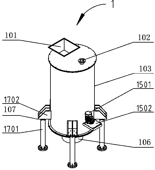
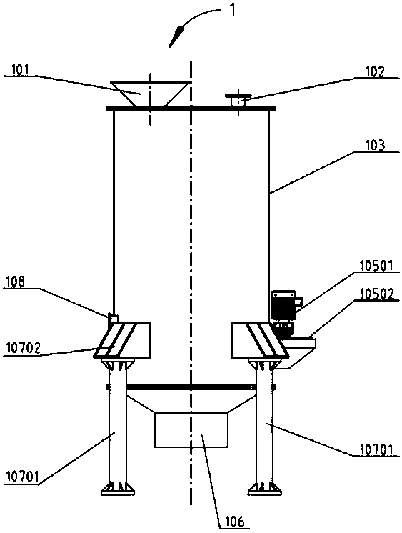
[0041] On the basis of the foregoing embodiments, in this embodiment, the pyrolysis gasifier 1 includes a feed inlet 101, a cracked gas outlet 102, a pyrolysis gasifier furnace body 103, a rotary grate 104, and the grate drives Device 105, slag outlet 106, furnace support structure 107, manhole 108 and pyrolysis gasifier burner 109; feed inlet 101 and cracked gas outlet 102 are located at the upper end of pyrolysis gasifier furnace body 103, and the rotary grate 104 is located at the bottom of the pyrolysis gasification furnace body 103, and the grate driving device 105 is located at the lower side outside the pyrolysis gasification furnace body 103; the slag outlet 106 is arranged at the bottom of the pyrolysis gasification furnace body 103, The bottom of the pyrolysis gasification furnace body 103 is connected to the furnace body support structure 107; the manhole 108 is located on the lower side outside the pyrolysis gasification furnace body 103 and is not on the same side ...


PUM


Abstract

The invention provides a waste pyrolysis gasification system. The system comprises a pyrolysis gasifier, a pyrolysis gas combustion chamber, a dust removal unit, a deacidification unit, a chimney anda waste heat recycling unit; the outlet of the lower end of the pyrolysis gasifier 1 communicates with the gas inlet of the pyrolysis gas combustion chamber, and the pyrolysis gasifier communicates with the pyrolysis gas combustion chamber through the waste heat recycling unit; and the outlet of the pyrolysis gas combustion chamber is connected with the inlet of the dust removal unit, an outlet ofthe dust removal unit is connected with the inlet of the deacidification unit, and the outlet of the deacidification unit is connected with the chimney. The system is suitable for the technical fieldof waste pyrolysis gasification, the waste can be treated without the pretreatment processes such as classification and drying, the waste can be prevented from being stacked up in the pyrolysis gasifier so that the system can operate continuously and stably, the operation efficiency can be improved, the service life of the grate can be prolonged, the operation cost can be reduced, the modularization and miniaturization design of equipment can be realized, the equipment flexibility can be improved, and the requirement of waste treatment of different scales can be met.

Description

technical field [0001] The invention belongs to the technical field of garbage pyrolysis and gasification, and in particular relates to a garbage pyrolysis gasification system. Background technique [0002] With the continuous development of social economy and the gradual expansion of population size and urbanization, the generation of urban domestic waste continues to increase, and the pollution caused by domestic waste to the environment is becoming more and more serious. Domestic waste, a serious public hazard, has become a serious public hazard in today's world. Big and tough questions. At present, there are three basic ways to deal with domestic waste: composting, landfilling, and incineration. Among them, the composting method has high requirements on the organic matter content in the garbage, and the heavy metal content in the fertilizer is not easy to control, which is likely to cause pollution of the farmland soil, and the sales radius and competitiveness of the fe...

Claims


Application Information

Patent Timeline
Patent Type & Authority Patents(China)
IPC IPC(8): F23G5/027F23G5/44F23G5/46F23J15/02
CPCF23G5/002F23G5/006F23G5/027F23G5/44F23G5/46F23G2201/302F23G2201/303F23G2206/10F23J15/02F23J15/022
Inventor 潘利祥李朝晖舒宁赵良庆张勋
Owner CECEP ENVIRONMENTAL PROTECTION EQUIP CO LTD
Why Eureka
Try Eureka