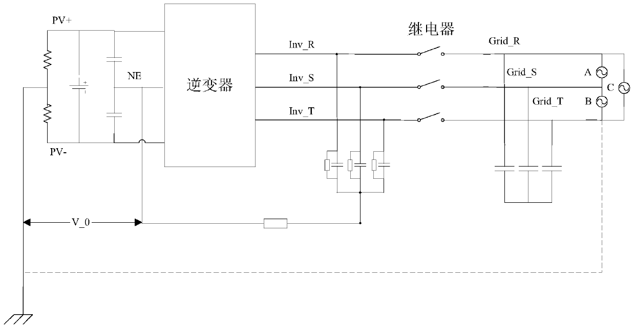
A detection method and device for an inverter grid-connected AC relay
A technology of AC relay and detection method, applied in circuit breaker testing, instrumentation, measuring electricity and other directions, can solve problems such as inconsistency, relay adhesion, short-circuit three-phase grid impedance, etc.
- Summary
- Abstract
- Description
- Claims
- Application Information
AI Technical Summary
Problems solved by technology
Method used
Image
Examples
Embodiment 1
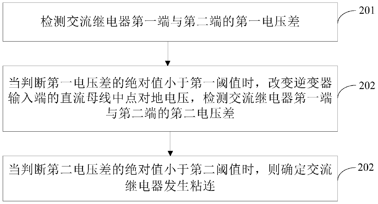
[0075] see figure 2 , is a flowchart of a detection method for an inverter grid-connected AC relay provided in this embodiment.
[0076] The first end of the AC relay is connected to the output end of the inverter, and the second end of the AC relay is connected to the AC grid. The method includes:
[0077] Step 201: Detect a first voltage difference between the first terminal and the second terminal of the AC relay.
[0078] Use the voltage measuring device to detect the voltage of the AC relay on the output side of the inverter and the voltage of the AC relay on the AC grid side, that is, use the voltage measuring device to detect the voltages of the first terminal and the second terminal of the AC relay respectively, and convert the voltage of the first terminal to Make a difference with the voltage at the second terminal to obtain a first voltage difference.
[0079] Step 202: When it is judged that the absolute value of the first voltage difference is smaller than the ...
Embodiment 2
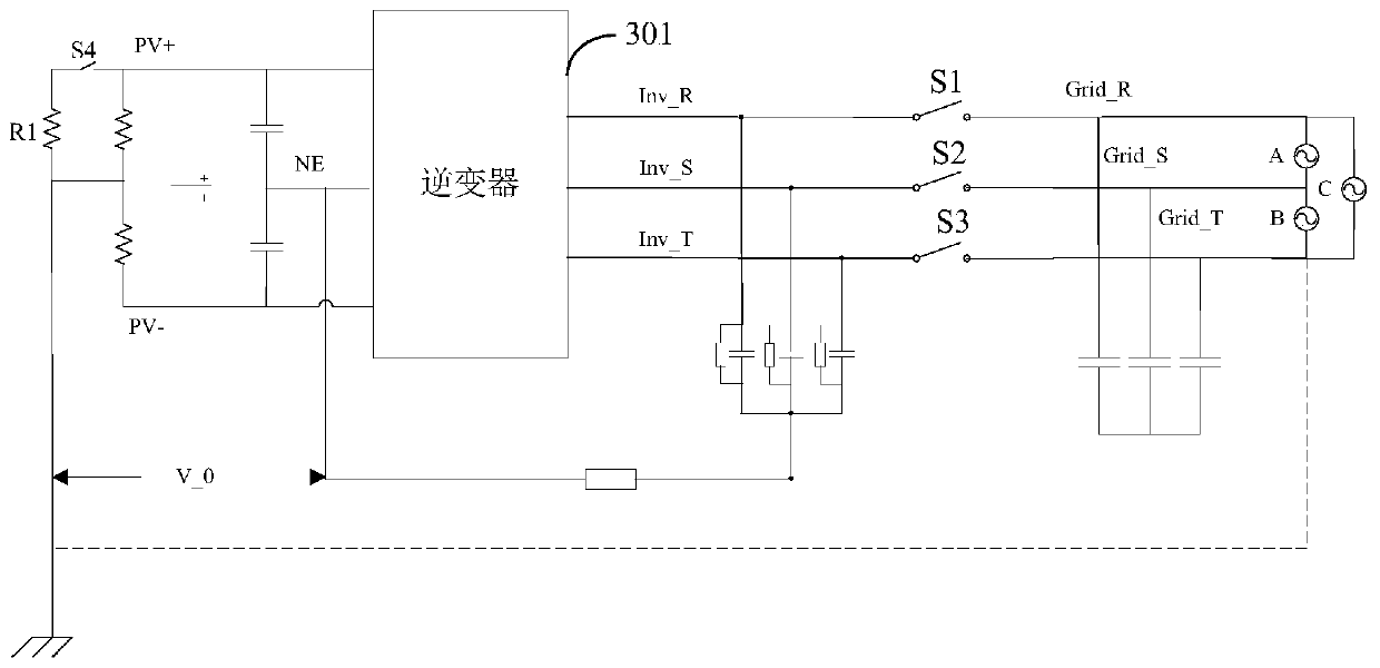
[0090] Such as image 3 As shown, it is a topological structure diagram of a three-phase inverter in a power supply neutral point ungrounded system, in which a first controllable switch S4 and an additional resistor R1 are added.
[0091] A first controllable switch S4 and an additional resistor R1 are connected in series between the positive input terminal of the inverter 301 and the ground.
[0092] By controlling the switching state of the first controllable switch S4, the voltage of the midpoint NE of the DC bus at the input end of the inverter 301 to the ground is changed.
[0093] It should be noted that, in the three-phase circuit, the AC relays are arranged between the output terminal of the inverter and the input terminal of the AC grid, which are respectively S1, S2 and S3.
[0094] Specifically, calculate the difference between the voltage of the AC relay on the inverter output side and the voltage of the AC relay on the AC grid side, first control the first contro...
Embodiment 3
[0108] Such as Figure 5 Shown is a topological structure diagram of a three-phase inverter in a power supply neutral point ungrounded system using the second method.
[0109] A bus discharge circuit is added in this structure.
[0110] A bus discharge circuit is connected between the positive bus or negative bus and the midpoint NE of the DC bus, and the voltage of the midpoint NE of the DC bus to ground is changed by controlling the conduction state of the bus discharge circuit.
[0111] Specifically, the bus discharge circuit may be composed of a controllable switch S5 connected in series with an additional resistor R2. When the controllable switch S5 is turned off, it is judged whether the absolute value of the first voltage difference between the first end and the second end of the AC relay is less than the first threshold, and when the absolute value of the first voltage difference is less than the first threshold, the bus discharge is closed The controllable switch S5...
PUM
 Abstract
Description
Claims
Application Information
 - R&D
- Intellectual Property
- Life Sciences
- Materials
- Tech Scout
- Unparalleled Data Quality
- Higher Quality Content
- 60% Fewer Hallucinations
Browse by: Latest US Patents, China's latest patents, Technical Efficacy Thesaurus, Application Domain, Technology Topic, Popular Technical Reports.
© 2025 PatSnap. All rights reserved.Legal|Privacy policy|Modern Slavery Act Transparency Statement|Sitemap|About US| Contact US: help@patsnap.com


