
Lens driving module

A technology of optical components and driving modules, applied in the directions of optical components, optical components, electrical components, etc., can solve the problems of large pulling force, difficulty in reducing the wire diameter of the lifting ring, and difficulty in achieving shake compensation, and achieve the effect of reducing thickness and reducing thickness.

Active Publication Date: 2018-04-24
TDK TAIWAN
View PDF5 Cites 10 Cited by
  • Summary
  • Abstract
  • Description
  • Claims
  • Application Information

AI Technical Summary

Problems solved by technology

However, when the thickness of the electronic device is reduced to make it lighter and thinner, the length of the above-mentioned suspension ring wire will be reduced, which in turn will generate a large pulling force, making it difficult to achieve the above-mentioned shake compensation function.
Since it is difficult to reduce the wire diameter of the ring wire nowadays, how to solve the aforementioned problems has become an important issue

Method used

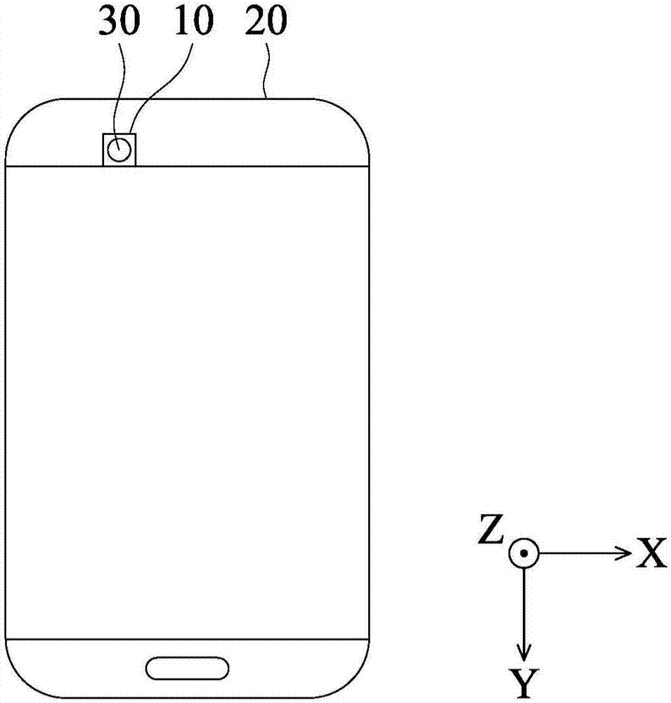
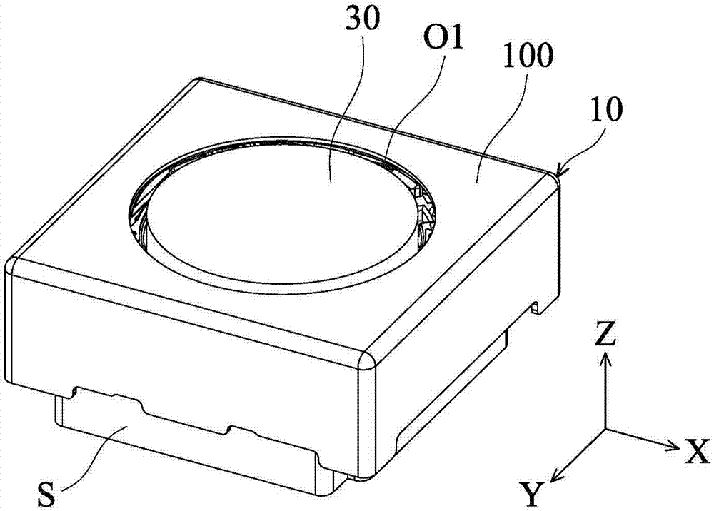
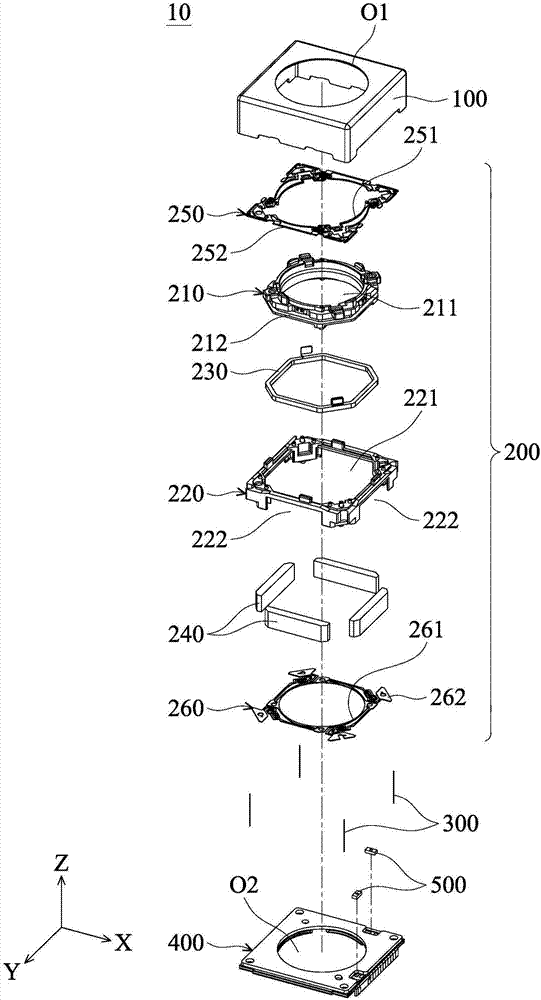

Image

  • Lens driving module
  • Lens driving module
  • Lens driving module

Examples


Embodiment Construction

[0100] The optical element driving module of the embodiment of the present invention is described below. It should be readily appreciated, however, that the embodiments of the invention provide many suitable inventive concepts that can be implemented in a wide variety of specific contexts. The specific embodiments disclosed are merely illustrative of specific ways to use the invention and do not limit the scope of the invention.

[0101] Unless otherwise defined, all terms (including technical and scientific terms) used herein have the same meaning as commonly understood by one of ordinary skill in the art of this disclosure. It is understood that these terms, such as those defined in commonly used dictionaries, should be interpreted as having a meaning consistent with the background or context of the related art and the present disclosure, rather than in an idealized or overly formal manner Interpretation, unless specifically defined herein.

[0102] First, please also refe...


PUM


Abstract

An optical member driving module is provided, including a moving mechanism, a base, a suspension wire, and an electromagnetic driving mechanism for driving the moving mechanism to move relative to thebase. The moving mechanism includes an optical member holder, and the base has a first surface, a second surface, and an opening. The second surface faces the optical member holder and is opposite tothe first surface. The opening extends from the first surface to the second surface. The suspension wire extends through the opening, and the opposite ends of the suspension wire are respectively affixed to the first surface and the moving mechanism.

Description

technical field [0001] The invention relates to an optical element driving module. More specifically, the present invention relates to an optical element driving module having an eyelet wire. Background technique [0002] With the development of technology, many electronic devices (such as smart phones or digital cameras) now have the function of taking photos or recording videos. The use of these electronic devices is becoming more and more common, and they are developing towards the direction of convenience and thinner design, so as to provide users with more choices. [0003] The aforementioned electronic device with a camera or video recording function is usually provided with a lens driving module to drive a lens to move along an optical axis, thereby achieving autofocus and / or zoom functions. The light can pass through the aforementioned lens and form an image on a photosensitive module. [0004] In addition, some electronic devices also include components such as r...

Claims


Application Information

Patent Timeline
Patent Type & Authority Applications(China)
IPC IPC(8): G02B7/09G03B5/00H04N5/232G03B30/00
CPCG02B7/09G03B5/00H04N23/60H04N23/687
Inventor 游证凯陈怡和胡朝彰宋欣忠
Owner TDK TAIWAN
Learn More