BUCK-BOOST type DC converter and control method thereof

A technology of DC converter and control method, which is applied in the field of power supply, and can solve problems such as large dynamic loss, affecting efficiency, and changing

Active Publication Date: 2018-04-24
BEIJING XIAOMI PINECONE ELECTRONICS CO LTD
View PDF3 Cites 16 Cited by
  • Summary
  • Abstract
  • Description
  • Claims
  • Application Information

AI Technical Summary

Problems solved by technology

There are two problems with this solution, first: if the battery is full capacity, its output voltage will be relatively high, then the efficiency of the LDO will be very low, which will shorten the battery life and cause more heat
Second: If the battery capacity is getting lower and lower, its output voltage will also be lower and lower. When the voltage is lower than 3.3V, the LDO will not be able to output 3.3V voltage for system use. In order to ensure the stability and reliability of the system, The solution is generally when the battery voltage drops to about 3.6V, it will alarm for low battery, or even shut down directly
But the problem with this solution is that in the BUCK-BOOST mode, the power switches in the circuit will be turned on or off in pairs at the same time according to a certain timing (such as Image 6 P1 and P3 are turned on or off at the same time, P2 and P4 are turned on or off at the same time), so the dynamic loss is very large, which affects the efficiency
Moreover, due to the influence of factors such as the on-resistance of the switch tube and the parasitic resistance of the wiring, the effective value of the input voltage will change with the change of the load. That is to say, when the load becomes larger, the effective input voltage will decrease. This will cause the converter's operating mode to change depending on the input voltage
If the working mode of the converter is controlled according to the ideal relationship between the input voltage and the output voltage, it is obvious that the buck-boost type DC converter will not be in the best working state

Method used


Image

  • BUCK-BOOST type DC converter and control method thereof
  • BUCK-BOOST type DC converter and control method thereof
  • BUCK-BOOST type DC converter and control method thereof

Examples


Embodiment Construction

[0094] Specific embodiments of the present disclosure will be described in detail below in conjunction with the accompanying drawings. It should be understood that the specific implementations described here are only used to illustrate and explain the present disclosure, not to limit the present disclosure.

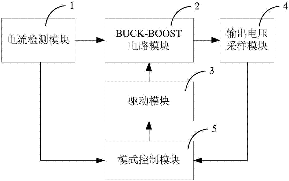
[0095] Such as figure 1 Shown is the functional block diagram of the BUCK-BOOST DC converter provided by the present invention. The BUCK-BOOST DC converter includes: a current detection module 1 , a BUCK-BOOST circuit module 2 , a drive module 3 , an output voltage sampling module 4 and a mode control module 5 . The current detection module 1 is connected to the BUCK-BOOST circuit module 2 for detecting the inductor current in the BUCK-BOOST circuit 1, and sends the current detection signal to the mode control module 5; the output The voltage sampling module 4 is connected to the output end of the BUCK-BOOST circuit module 2 for obtaining an output voltage sampling sig...


PUM


Abstract

The disclosure relates to a BUCK-BOOST type DC converter and a control method thereof; the converter comprises a BUCK-BOOST circuit module, a drive module, an output voltage sampling module, a mode control module and a current detection module; the current detection module is in middle phase connection with the BUCK-BOOST circuit module, used for detecting inductance current in the BUCK-BOOST circuit, and sending current detection signals to the mode control module; the mode control module can form a corresponding PWM mode control signal or a PSM mode control signal according to the current detection signal and an output voltage sample signal; according to the PWM mode control signal or the PSM mode control signal, the drive module drives the BUCK-BOOST circuit to work in a BUCK mode, a BOOST mode or a BUCK-BOOST mode under the PWM mode, or to work in the BUCK-BOOST mode under the PSM mode. The DC converter can output a stable voltage in a full load range, and the switch tube power consumption and circuit static loss can be reduced in a mode switching process, thus improving the conversion efficiency.

Description

technical field [0001] The present disclosure relates to the technical field of power supplies, and in particular, to a BUCK-BOOST DC converter and a control method thereof. Background technique [0002] With the rapid development of electronic technology, all kinds of mobile terminals represented by smart phones and tablet computers have entered thousands of households, and the industry is also making further technological development. It is hoped that through various functions and perfect and reliable Performance brings more convenience to people's life. Among them, standby time and terminal heating are the performances that the industry is trying to improve. At present, the standby time of most terminals is not long enough, and the problem of terminal heating still needs to be further optimized. In order to solve the above two problems, one method is to strive to increase the battery capacity, improve the thermal conductivity of materials, etc.; the other method is to o...

Claims


Application Information

Patent Timeline
Patent Type & Authority Applications(China)
IPC IPC(8): H02M3/158H02H7/12
CPCH02H7/1213H02M3/1582H02M1/0058Y02B70/10
Inventor 陈进
Owner BEIJING XIAOMI PINECONE ELECTRONICS CO LTD
Why Eureka
Try Eureka