Inverter for restraining leakage current and inverter system

An inverter, leakage current technology, used in control/regulation systems, conversion equipment without intermediate conversion to AC, regulating electrical variables, etc.

Active Publication Date: 2018-04-24
SUNGROW POWER SUPPLY CO LTD
View PDF6 Cites 13 Cited by
  • Summary
  • Abstract
  • Description
  • Claims
  • Application Information

AI Technical Summary

Problems solved by technology

However, using this method to solve the problem of high-frequency leakage current cannot be completely solved. During the dead time, a peak leakage current with a second switching frequency and a width close to the dead time will still be generated in the photovoltaic inverter.

Method used


Image

  • Inverter for restraining leakage current and inverter system
  • Inverter for restraining leakage current and inverter system
  • Inverter for restraining leakage current and inverter system

Examples


Embodiment 1

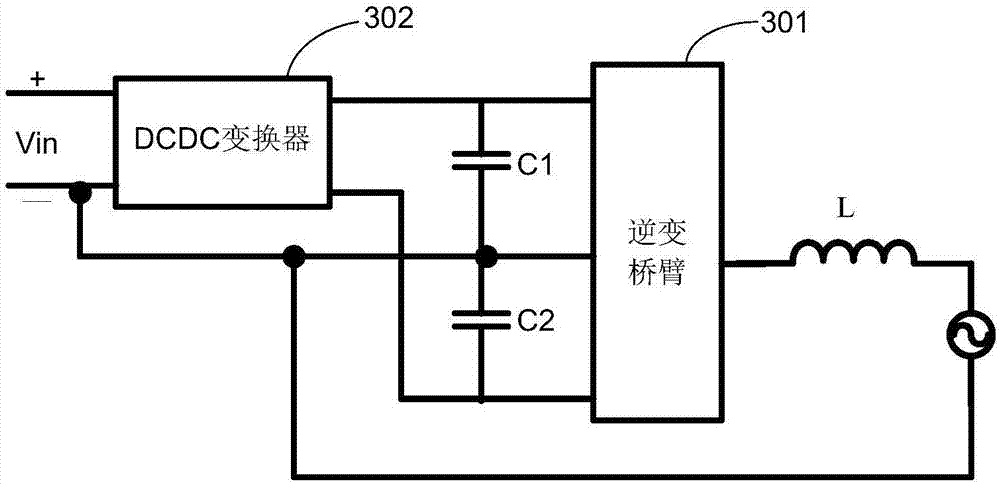
[0066] see image 3 , is a structure diagram of an inverter for suppressing leakage current provided in the embodiment of the present application, the inverter includes: a multilevel inverter bridge arm 301, a DCDC converter 302, a first capacitor C1 and a second capacitor C2 .

[0067] The inverter provided in the embodiment of the present application is a multi-level inverter, therefore, the inverter bridge arm in the inverter is a multi-level inverter bridge arm.

[0068] The positive input terminal and the negative input terminal of the multilevel inverter bridge arm 301 are respectively connected to the positive output terminal and the negative output terminal of the DCDC converter 302 .

[0069] The first capacitor C1 and the second capacitor C2 are connected in series between the positive input end and the negative input end of the multilevel inverter bridge arm 301 .

[0070] The midpoint of the multilevel inverter bridge arm 301 is connected to the common point of t...

Embodiment 2

[0093] see Figure 5 , is a structure diagram of an inverter for suppressing leakage current provided in this embodiment.

[0094] When the midpoint of the multilevel inverter bridge arm 301 is connected to the negative terminal of the DC power supply Vin, the midpoint of the multilevel inverter bridge arm 301 can be connected to the negative terminal of the DC power supply Vin through the second switch S2.

[0095] When it is judged that the leakage current of the inverter is greater than the preset current value, the second switch S2 is closed, otherwise, it is opened.

[0096] In this embodiment, it is judged whether the leakage current in the inverter that suppresses the leakage current is greater than the preset current value. A large leakage current closes the second switch S2 disposed between the midpoint of the multilevel inverter bridge arm 301 and the negative terminal of the DC power supply Vin. Since the midpoint of the multilevel inverter bridge arm 301 is alway...

Embodiment 3

[0119] The DCDC converter included in the inverter for suppressing leakage current provided in the embodiment of the present application is at least one of the following:

[0120] Buck, Boost, Buckboost, Cuk, Sepic, Zeta, Forward Converter, Flyback Converter, Push-Pull Converter and Full Bridge Converter.

[0121] The following introduces several optional forms of DCDC converters provided by the embodiments of the present application in conjunction with the accompanying drawings:

[0122] Such as Figure 11 As shown in FIG. 1 , it is a structural diagram of an inverter using a Buckboost converter as a DCDC converter provided in this embodiment.

[0123] The positive terminal of the DC power supply is connected to the positive input terminal of the Buckboost converter, and the negative terminal of the DC power supply is connected to the negative input terminal of the Buckboost converter. When the switch S1 is closed, the DC power supply charges the inductor L1 in the Buckboost ...


PUM


Abstract

The invention discloses an inverter for restraining the leakage current, wherein the inverter comprises a multi-level inverter bridge arm, a DC-DC converter, a first capacitor and a second capacitor.The positive input end and the negative input end of the DC-DC converter are respectively connected with the positive end and the negative end of a DC power supply. The positive input end and the negative input end of the inverter bridge arm are connected with the positive output end and the negative output end of the DC-DC converter respectively. The output end of the multi-level inverter bridgearm is connected with an AC power grid. The first capacitor and the second capacitor are connected in series and then are connected between the positive input end and the negative input end of the multi-level inverter bridge arm. The middle point of the multi-level inverter bridge arm is connected with a common point between the first capacitor and the second capacitor. The middle point of the multi-level inverter bridge arm is connected with the positive end or the negative end of the DC power supply. The N line of the AC power grid is connected with the middle point of the multi-level inverter bridge arm. Namely, the inverter for restraining the leakage current and provided by the invention is used for directly grounding the positive end or the negative end of the DC power supply. Therefore, the leakage current of the inverter is approximately zero.

Description

technical field [0001] The invention relates to the technical field of power electronics, in particular to an inverter and an inverter system for suppressing leakage current. Background technique [0002] In a photovoltaic power generation system, it is generally necessary to use a photovoltaic inverter to convert the direct current generated by the solar panel into alternating current that can be incorporated into the AC grid. During the conversion process, the direct current output by the solar panel needs to be input to the DCDC converter. Get the right DC power so that the inverter can convert that DC power into AC power that can be used by the grid. [0003] In order to reduce the loss caused by the operation of the photovoltaic inverter itself, the photovoltaic inverter usually adopts a transformerless inverter topology and a unipolar modulation method. However, a traditional bridge inverter, such as an H-bridge inverter, will generate a large high-frequency common-mo...

Claims


Application Information

Patent Timeline
Patent Type & Authority Applications(China)
IPC IPC(8): H02M7/5387H02M7/487H02M1/32H02M3/158H02M3/00H02M3/07H02M3/335
CPCH02M1/32H02M3/00H02M3/005H02M3/07H02M3/1582H02M3/33523H02M7/487H02M7/53871H02M1/322H02M3/072
Inventor 俞雁飞倪华
Owner SUNGROW POWER SUPPLY CO LTD
Why Eureka
Try Eureka