Time synchronization method for fault indicator of transient wave record type

A technology for fault indicator and time synchronization, which is applied in the direction of synchronization device, synchronization device, and synchronization error correction, etc. problems such as the accuracy of the state zero-sequence current, to achieve the effect of solving time synchronization accuracy and energy efficiency, reducing the number, and ensuring accuracy

Active Publication Date: 2018-04-24
WUHAN ZHONGYUAN ELECTRONICS INFORMATION
View PDF9 Cites 17 Cited by
  • Summary
  • Abstract
  • Description
  • Claims
  • Application Information

AI Technical Summary

Problems solved by technology

According to the statistics of the State Grid, the time synchronization accuracy of the current transient recording type fault indicators of various manufacturers cannot reach the synchronization error of 100μs in the special detection, which will inevitably affect the accuracy of the synthesized transient zero-sequence current, resulting in single-phase The inaccurate judgment of the ground fault affects the application effect of the fault indicator of the transient recording type

Method used


Image

  • Time synchronization method for fault indicator of transient wave record type
  • Time synchronization method for fault indicator of transient wave record type
  • Time synchronization method for fault indicator of transient wave record type

Examples


Embodiment Construction

[0027] The technical solutions of the present invention will be further described in detail below in conjunction with the accompanying drawings and specific embodiments.

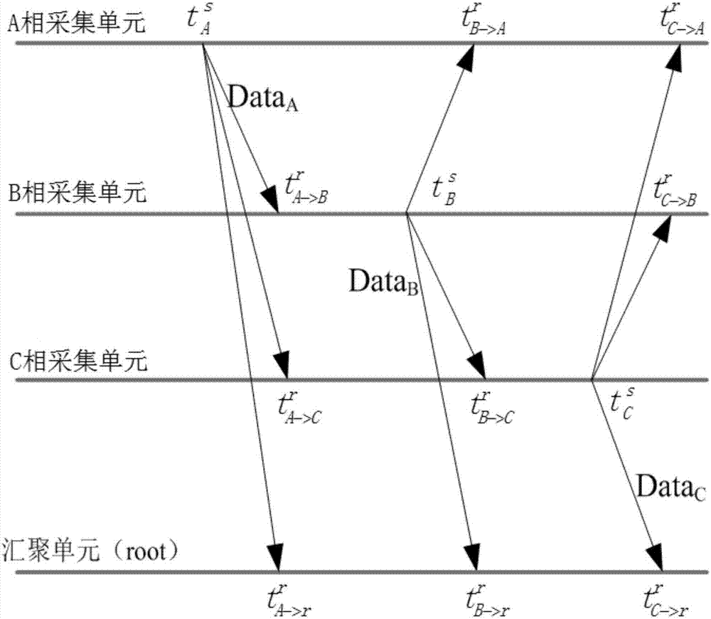
[0028] On the three phases A, B, and C at the same location of the overhead line, install the A-phase acquisition unit, B-phase acquisition unit, and C-phase acquisition unit respectively, and install the aggregation unit on the power tower close to the acquisition unit, the aggregation unit, and the A-phase acquisition unit. The acquisition unit, phase B acquisition unit and phase C acquisition unit are all equipped with 433MHz or 2.4GHz wireless communication modules, and each acquisition unit communicates with the other two acquisition units and the convergence unit through the wireless communication module.

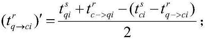
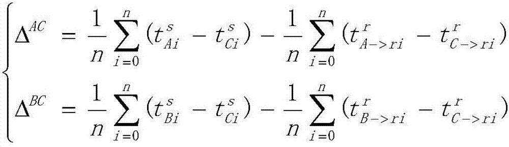
[0029] Step 1, when the A-phase acquisition unit, the B-phase acquisition unit and the C-phase acquisition unit are installed on the line to start working, first the convergence unit broadcasts a syn...


PUM


Abstract

The invention discloses a time synchronization method for a fault indicator of a transient wave record type, and the method comprises the steps that a convergence unit broadcasts a synchronization beacon frame to each collection unit for synchronization; each collection unit transmits a data frame comprising a synchronization byte to other collection units and the convergence unit, and each collection unit monitors the data frames of other collection units, and marks the data frames with the synchronization bytes; two collection units which transmit the data frames at first carry out the synchronization of local time with the collection unit which transmits the data frame at last according to the relative time drift and relative initial time difference; the convergence unit carries out thesynchronization of all data frames according to the obtained time difference. The method achieves the local synchronization of the collection units, and achieves the post-synchronization of the dataframes in the convergence unit.

Description

technical field [0001] The invention belongs to the technical field of state monitoring and fault location of power system distribution network, and in particular relates to a time synchronization method applied to a fault indicator of a transient recording type. Background technique [0002] In the distribution network system, there are many branches and complex operation conditions. When a short circuit or ground fault occurs, it is difficult to determine the fault section, which brings great difficulties to the maintenance work, especially in remote areas, and it takes time and effort to find it. With the advancement of distribution automation and rural power grid transformation in my country, fault indicators, as one of the technical means of distribution fault location, have been put into use in large quantities. Due to the low accuracy of traditional two-remote fault indicators for single-phase ground faults, the State Grid began to implement transient recorder fault i...

Claims


Application Information

Patent Timeline
Patent Type & Authority Applications(China)
IPC IPC(8): H04W56/00H04L7/00H04J3/06
CPCH04J3/0638H04L7/0016H04W56/001
Inventor 张文魁周任飞张林桥张恒舫刘三丰
Owner WUHAN ZHONGYUAN ELECTRONICS INFORMATION
Why Eureka
Try Eureka