Positioning device for force line measuring angle of osteotomy around knee
An angle positioning, knee joint technology, applied in application, bone drill guidance, medical science, etc., can solve the problems of increasing the dose of patients and surgeons, increasing the number of surgeons, prolonging operation time, etc., to reduce the number of fluoroscopy and radiation dose , Improving the safety of surgery and shortening the operation time
- Summary
- Abstract
- Description
- Claims
- Application Information
AI Technical Summary
Problems solved by technology
Method used
Image
Examples
Embodiment 1
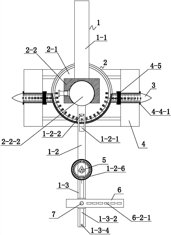
[0066] figure 1 It is a schematic diagram of the structure of the force line measuring angle positioning device used for osteotomy around the knee joint. Such as figure 1 As shown, a force line measurement angle positioning device for osteotomy around the knee joint, the positioning device includes an angle force line measurement rod 1 , a fixation assembly 2 , a support pin 3 and a splint support 4 .
[0067] The angleable force line measuring rod 1 includes a fixed rod 1-1, a first movable rod 1-2 and a second movable rod 1-3. One surface of the fixed assembly 2 is connected with one end of the fixed rod 1-1, and the opposite surface of the fixed rod 1-1 and the fixed assembly 2 on the fixed assembly 2 is movably connected with one end of the first movable rod 1-2. The other end of the movable rod 1-2 is pivotally connected to the second movable rod 1-3 through the pivot shaft 5 . The second movable rod 1-3 can swing horizontally relative to the first movable rod 1-2, and...
Embodiment 2
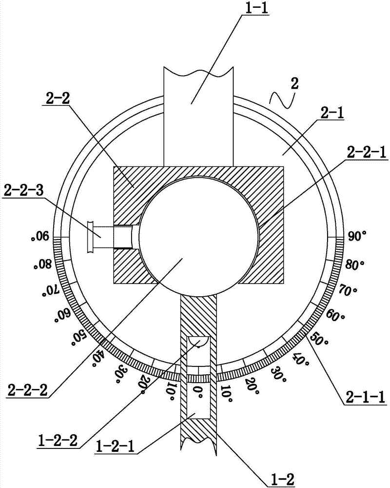
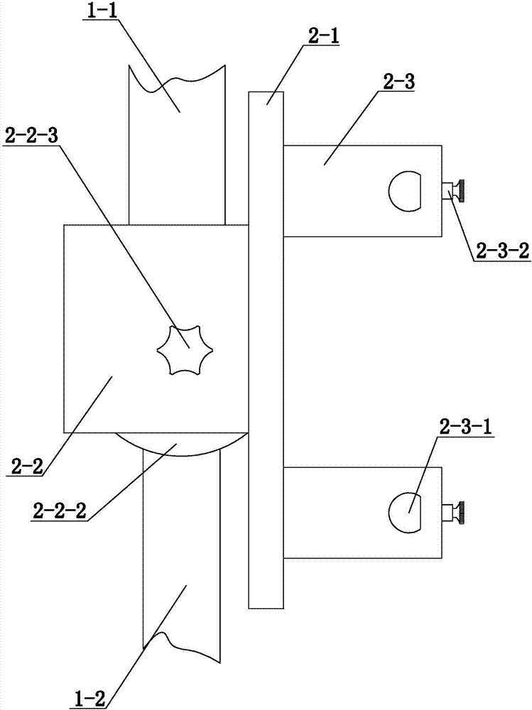
[0084] Embodiment 2 On the basis of Embodiment 1, a more preferred structure of force line measurement angle positioning device for osteotomy around the knee joint is provided, such as figure 2 and image 3 shown. Specifically, Embodiment 2 further defines that the fixing assembly 2 includes a base 2-1 and a fixing platform 2-2 connected to the upper surface of the base 2-1.
[0085] The fixed table 2-2 is provided with a spherical crown-shaped cavity 2-2-1, and the cavity 2-2-1 runs through the connection surface between the first movable rod 1-2 and the fixed component 2, and is located in the cavity on the penetration surface. The maximum pitch of the notches of the cavity 2-2-1 is smaller than the maximum diameter of the cavity 2-2-1. The plane of the cavity 2-2-1 is parallel to the base 2-1, and is attached to the base 2-1.
[0086] The cavity 2-2-1 is provided with a rotary block 2-2-2 that cooperates with the cavity 2-2-1 and can rotate horizontally. The rotary bloc...
Embodiment 3
[0093] Embodiment 3 On the basis of Embodiment 1 or Embodiment 2, a more preferred structure of force line measurement angle positioning device for osteotomy around the knee joint is provided, such as Figure 4 , Figure 6 and Figure 7 shown. Specifically, this embodiment 3 further defines that the first movable rod 1-2 is provided with a threaded through hole 1-2-3 matched with the pivot shaft 5 . The end surface of the first movable rod 1-2 close to the end of the second movable rod 1-3 is recessed with a pivotal cavity 1-2-4 along the axial direction, and the pivotal cavity 1-2-4 runs through the second movable rod along the horizontal direction. A movable rod 1-2, the pivoting cavity 1-2-4 communicates with the threaded through hole 1-2-3. A pit 1-2-5 is provided on the inner wall of the pivotal cavity 1-2-4 close to the end surface.
[0094] One end of the second movable rod 1-3 is provided with a pivotal projection 1-3-1 that cooperates with the pivotal cavity 1-2-4...
PUM
 Abstract
Description
Claims
Application Information
 - R&D
- Intellectual Property
- Life Sciences
- Materials
- Tech Scout
- Unparalleled Data Quality
- Higher Quality Content
- 60% Fewer Hallucinations
Browse by: Latest US Patents, China's latest patents, Technical Efficacy Thesaurus, Application Domain, Technology Topic, Popular Technical Reports.
© 2025 PatSnap. All rights reserved.Legal|Privacy policy|Modern Slavery Act Transparency Statement|Sitemap|About US| Contact US: help@patsnap.com


