Eureka AIR delivers breakthrough ideas for toughest innovation challenges, trusted by R&D personnel around the world.

A multifunctional tooling fixture

A fixture and multi-functional technology, applied in the field of small parts processing, can solve the problems of difficult to overcome processing errors, low workpiece processing efficiency and product qualification rate, high labor intensity, etc., to overcome unstable processing quality, save clamping and Tool change time, overcoming the effect of low machining efficiency

Inactive Publication Date: 2019-05-21
SHANGHAI DIANJI UNIV
View PDF5 Cites 0 Cited by
  • Summary
  • Abstract
  • Description
  • Claims
  • Application Information

AI Technical Summary

Problems solved by technology

[0003] The existing processing procedures are scattered, and the artificial long-term continuous single sitting posture, continuous fixed repetitive labor, high labor intensity, serious fatigue damage to some parts of the body, low processing efficiency and product qualification rate of the workpiece; and due to the difference in personnel technology, it is difficult to overcome Processing errors caused by humans make it difficult to increase the pass rate of inspection and detection, and it is difficult to maintain stable quality

Method used


Image

  • A multifunctional tooling fixture
  • A multifunctional tooling fixture
  • A multifunctional tooling fixture

Examples


Embodiment Construction

[0034] In the following description, numerous specific details are given in order to provide a more thorough understanding of the present invention. It will be apparent, however, to one skilled in the art that the present invention may be practiced without one or more of these details. In other examples, some technical features known in the art are not described in order to avoid confusion with the present invention.

[0035] In order to thoroughly understand the present invention, detailed steps and detailed structures will be provided in the following description, so as to illustrate the technical solution of the present invention. Preferred embodiments of the present invention are described in detail below, however, the present invention may have other embodiments besides these detailed descriptions.

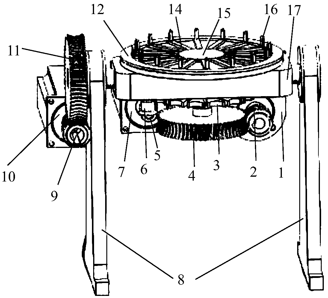
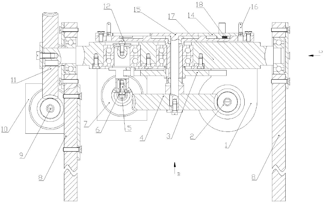
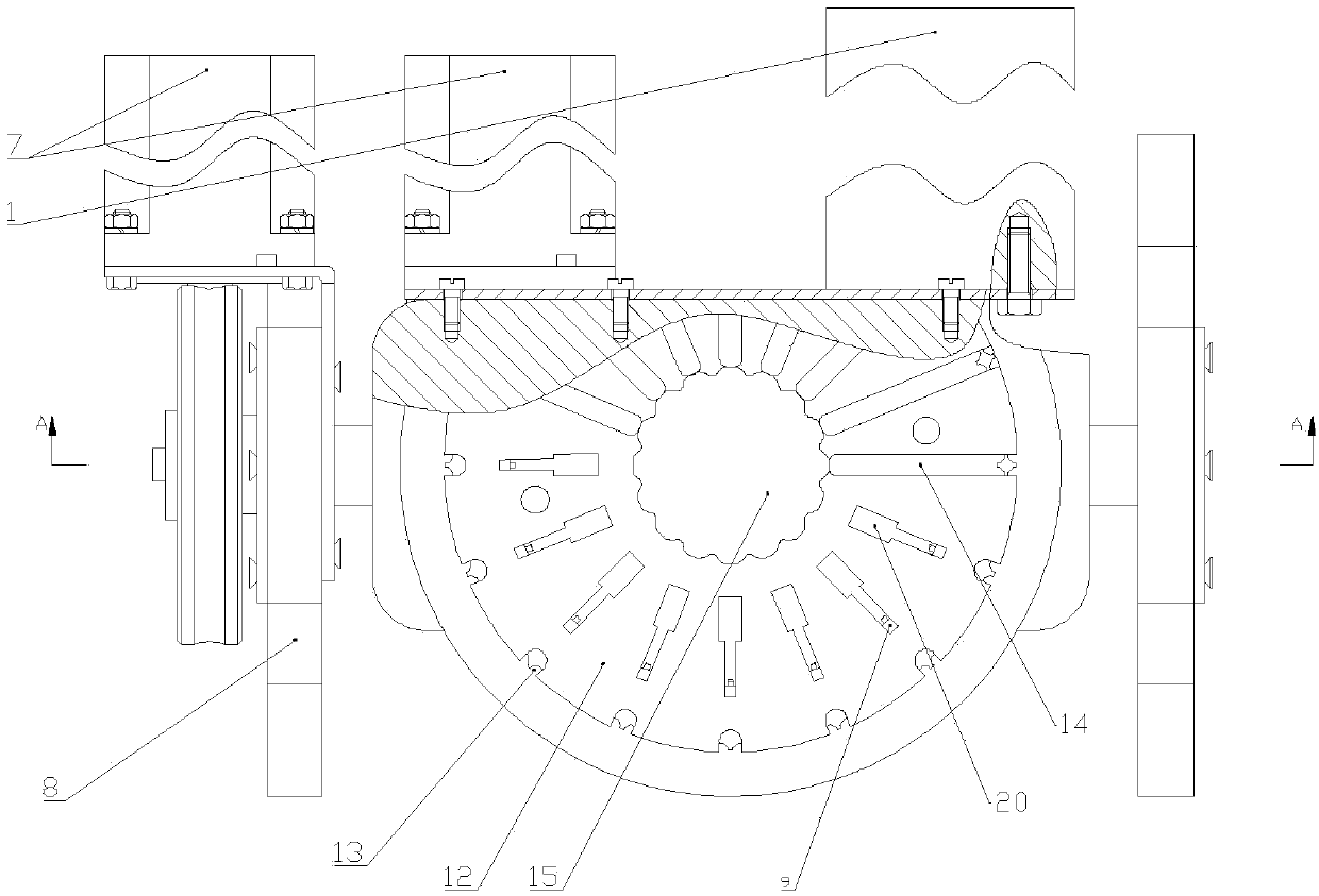
[0036] The invention provides a kind of multi-function fixture, refer to Figure 1-4 shown, including:

[0037] The support base, the support base is composed of two brack...


PUM


Abstract

The invention provides a multifunctional tool fixture. The multifunctional tool fixture comprises a supporting base, a rotating table, a turntable, a rotating wheel and a third driving device, whereinthe supporting base is composed of two supports; rotary shafts at the two ends of the rotating table are fixed to the supports correspondingly; the turntable is mounted on the rotating table, a firstdriving device mounted at the bottom of the rotating table drives the turntable to rotate, and a plurality of sliding blocks capable of moving in the radial direction and a plurality of clamping blocks corresponding to the multiple sliding blocks in position and arranged on the inner side of the edge of the turntable are arranged on the turntable around the axis of the turntable; the rotating wheel is mounted on the turntable and is coaxial with the turntable, a circle of inward concave grooves is formed in the outer edge face of the rotating wheel, cams are arranged between every two adjacent grooves, the rotating wheel is driven to rotate by a second driving device mounted at the bottom of the rotating table, and the outmost edge of the rotating wheel pushes the sliding blocks to slideoutwards and abut against the clamping blocks; and the third driving device drives the rotating table to swing or rotate along the rotary shafts of the rotating table. The multifunctional tool fixturecan improve the machining efficiency of parts and increase the product yield, the machining quality is ensured, and the labor intensity of manual operation is relieved.

Description

technical field [0001] The invention relates to the field of small parts processing, in particular to a multifunctional tooling fixture. Background technique [0002] At present, the processing of small parts is mainly completed manually, that is, through manual operation, different contents are processed separately on multiple single-function machine tools. The tooling adopted is also just a simple fixture. [0003] The existing processing procedures are scattered, and the artificial long-term continuous single sitting posture, continuous fixed repetitive labor, high labor intensity, serious fatigue damage to some parts of the body, low processing efficiency and product qualification rate of the workpiece; and due to the difference in personnel technology, it is difficult to overcome Processing errors caused by humans make it difficult to increase the pass rate of inspection and detection, and it is difficult to maintain stable quality. Contents of the invention [0004...

Claims


Application Information

Patent Timeline
Patent Type & Authority Patents(China)
IPC IPC(8): B23Q1/30B23Q3/06
CPCB23Q1/30B23Q3/061
Inventor 侯培红何敏
Owner SHANGHAI DIANJI UNIV
Why Eureka
Eureka Blog
Learn More