Correction method of laser drilling machine and laser drilling machine adopting correction method

A technology of laser drilling and calibration method, which is applied in the direction of laser welding equipment, welding equipment, metal processing equipment, etc., and can solve the problems of processing position deviation, reducing processing accuracy, and reducing production tact

Active Publication Date: 2021-06-01
SUZHOU VEGA TECH CO LTD
View PDF8 Cites 1 Cited by
  • Summary
  • Abstract
  • Description
  • Claims
  • Application Information

AI Technical Summary

Problems solved by technology

[0003]However, when the laser drilling machine uses laser to process the workpiece, with the long-term use of the vibrating mirror, its accuracy will be affected by the ambient temperature, humidity, vibration, etc. External factors and its own temperature drift change, and overall drift occurs. For example, a certain galvanometer will drift by 0.6mrad under 8 hours of long-term work. Calculated according to the focal length of the 100mmF-Theta le

Method used


Image

  • Correction method of laser drilling machine and laser drilling machine adopting correction method
  • Correction method of laser drilling machine and laser drilling machine adopting correction method
  • Correction method of laser drilling machine and laser drilling machine adopting correction method

Examples


Embodiment Construction

[0035] Embodiments of the present invention are described in detail below, examples of which are shown in the drawings, wherein the same or similar reference numerals designate the same or similar elements or elements having the same or similar functions throughout. The embodiments described below by referring to the figures are exemplary only for explaining the present invention and should not be construed as limiting the present invention.

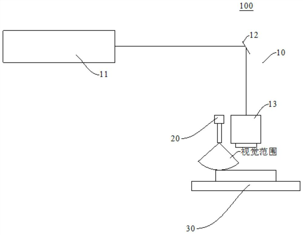
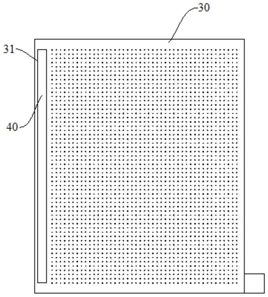
[0036] Refer below Figure 1-Figure 6 The calibration method of the laser drilling machine 100 and the laser drilling machine 100 according to the embodiment of the present invention will be described.

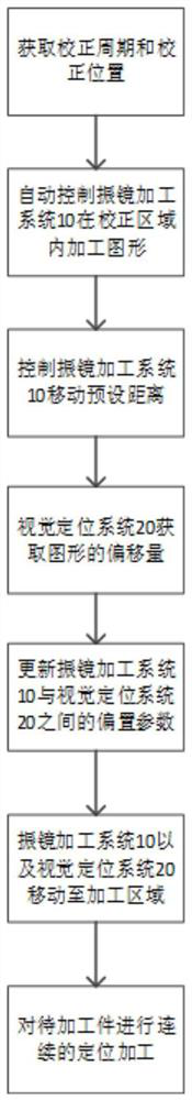
[0037] Such as figure 1 As shown, the calibration method of the laser drilling machine 100 according to the embodiment of the first aspect of the present application.

[0038] The correction method includes: obtaining the correction cycle and the correction position, automatically controlling the galvanometer processing system 10 to pr...


PUM


Abstract

The invention discloses a correction method of a laser drilling machine and the laser drilling machine adopting the correction method. The laser drilling machine comprises a galvanometer machining system, a visual positioning system in linkage with the galvanometer machining system and a workbench, and the workbench is provided with a correction area and a machining area. The correction method comprises the following steps: acquiring a correction period and a correction position; automatically controlling the galvanometer machining system to process a graph in the correction area according to the correction period and the correction position, and controlling the galvanometer machining system to move by a preset distance after machining is completed so as to enable the visual positioning system to obtain the offset of the graph; automatically updating an offset parameter between the galvanometer machining system and the visual positioning system according to the offset; and conducting continuous positioning machining on a workpiece to be machined in the machining area through the laser drilling machine by using the updated offset parameters. Therefore, the machining precision and the machining efficiency of the laser drilling machine can be improved.

Description

technical field [0001] The invention relates to the technical field of laser drilling machines, in particular to a calibration method for a laser drilling machine and a laser drilling machine using the same. Background technique [0002] In related technologies, with the development of society, people have higher and higher requirements for processing precision while requiring improvement in production efficiency. Laser drilling machine is an industrial production equipment that needs to take into account both high production efficiency and high precision. [0003] However, when the laser drilling machine uses the laser to process the workpiece, with the long-term use of the galvanometer, its accuracy will change due to external factors such as ambient temperature, humidity, vibration, and its own temperature drift, and there will be overall drift, such as : A certain type of galvanometer will drift 0.6mrad under long-term work for 8 hours. According to the calculation of t...

Claims


Application Information

Patent Timeline
IPC IPC(8): B23K26/382B23K26/70
CPCB23K26/382B23K26/702
Inventor 卢勇勇孟凡辉
Owner SUZHOU VEGA TECH CO LTD
Why Eureka
Try Eureka