
Waste cutting fluid purification treatment system

Pending Publication Date: 2019-07-05
DALIAN JIAOTONG UNIVERSITY
View PDF3 Cites 0 Cited by
  • Summary
  • Abstract
  • Description
  • Claims
  • Application Information

AI Technical Summary

Problems solved by technology

[0004] It is precisely because the cutting fluid will cause pollution and damage to the environment and the human body, the use of cutting fluid and waste liquid treatment have been increasingly restricted by environmental protection regulations

Method used


Image

  • Waste cutting fluid purification treatment system

Examples


Embodiment Construction

[0019] Embodiments of the present invention will be further described in detail below in conjunction with the accompanying drawings and examples. The following examples are used to illustrate the present invention, but should not be used to limit the scope of the present invention.

[0020] In the description of the present invention, it should be noted that the terms "center", "longitudinal", "transverse", "upper", "lower", "front", "rear", "left", "right", " The orientations or positional relationships indicated by "vertical", "horizontal", "top", "bottom", "inner" and "outer" are based on the orientations or positional relationships shown in the drawings, and are only for the convenience of describing the present invention and Simplified descriptions, rather than indicating or implying that the device or element referred to must have a particular orientation, be constructed and operate in a particular orientation, and thus should not be construed as limiting the invention. ...


PUM


Abstract

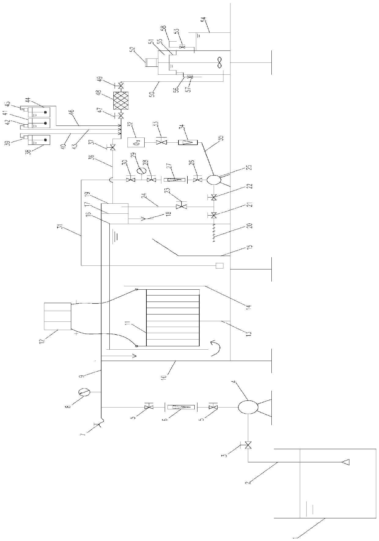
The invention relates to the technical field of machining wastewater treatment, in particular to a waste cutting fluid purification treatment system, which comprises a waste cutting fluid collecting box, a waste cutting fluid inlet pipe, a sewage pump, a waste cutting fluid outlet pipe, a shell, an electrode group, a direct current power supply, a first partition plate, a second partition plate, athird partition plate, a floating oil sludge collecting groove, a liquid outlet collecting pipe, a vortex pump, a gas conveying pipe, an ozone generator, a container water pipe, a first liquid outletpipe, a liquid outlet collecting box, a second liquid outlet pipe, an alkali liquor conveying pipe, an alkali liquor metering pump, an alkali liquor box, an emulsion conveying pipe, an emulsion metering pump, an emulsion box, an antirust conveying pipe, an antirust metering pump, an antirust box, a mixer, a third liquid outlet pipe, a mixing reaction box, a blender, a floating oil collecting weirand a fourth liquid outlet pipe. By the adoption of the waste cutting fluid purification treatment system, the principle of electrolysis and coagulation can be utilized to carry out various physicaland chemical actions such as redox, neutralization, coagulation, air flotation separation and the like on pollutants in the wastewater, so that sewage treatment is completed rapidly and effectively.

Description

technical field [0001] The invention relates to the technical field of machining wastewater treatment, in particular to a waste cutting fluid purification treatment system. Background technique [0002] In the process of modern metal processing, emulsified cutting fluid is an industrial liquid used to improve the cutting effect. Emulsified cutting fluid is widely used because of its good cooling, lubrication, anti-rust, anti-corrosion, cleaning and other functions. During use, the emulsified cutting fluid decomposes to varying degrees and deteriorates, resulting in reduced performance. Therefore, new emulsified cutting fluid should be replaced regularly. [0003] With the rapid development of industry, the discharge of this oily sewage is increasing day by day. In addition to the hazards of general oily wastewater, waste emulsions are highly dispersed in water due to the action of surfactants, which are easier for animals, plants and aquatic organisms to absorb, and surfact...

Claims


Application Information

Patent Timeline
Patent Type & Authority Applications(China)
IPC IPC(8): C02F9/06C02F103/16
CPCC02F9/00C02F1/78C02F1/24C02F1/66C02F1/463C02F2103/16
Inventor 许芝费庆志费洪剑范文新肖经伦邹之本
Owner DALIAN JIAOTONG UNIVERSITY
Learn More