Divided cavity and divided flow type exhaust pipe assembly and engine

An exhaust pipe and split flow technology, which is applied in the direction of engine components, combustion engines, machines/engines, etc., can solve the problem that the structure of the water jacket exhaust pipe assembly is not compact and unsightly, and the structure of the water jacket exhaust pipe is not compact and unsightly and other issues to achieve the effect of improving compactness and efficient cooling

Active Publication Date: 2018-04-27
WEICHAI POWER CO LTD
View PDF13 Cites 2 Cited by
  • Summary
  • Abstract
  • Description
  • Claims
  • Application Information

AI Technical Summary

Problems solved by technology

[0005] One object of the present invention is to provide a split-cavity and split-flow exhaust pipe assembly to solve the problem of uncompact and unsightly structure of the water jacket exhaust pipe in the prior art
[0006] Another object of the present invention is to provide an engine to solve the problem that the structure of the water jacket exhaust pipe assembly of the engine in the prior art is not compact and unsightly

Method used


Image

  • Divided cavity and divided flow type exhaust pipe assembly and engine
  • Divided cavity and divided flow type exhaust pipe assembly and engine
  • Divided cavity and divided flow type exhaust pipe assembly and engine

Examples


Embodiment Construction

[0047]The technical solutions of the present invention will be further described below in conjunction with the accompanying drawings and through specific implementation methods.

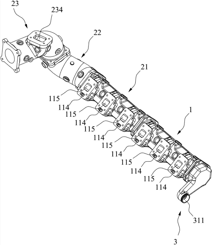
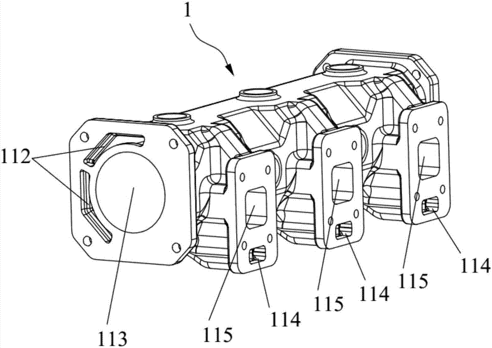
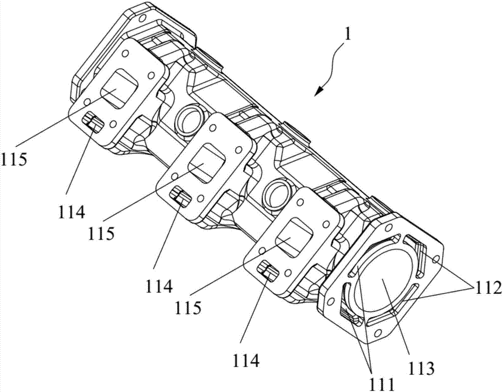
[0048] On the one hand, this embodiment provides a split-cavity split-flow exhaust pipe assembly, such as Figure 1-10 As shown, the exhaust pipe assembly is provided with exhaust chamber, air inlet 115, water inlet 114, water inlet chamber A111, water inlet chamber B, return water chamber, drain outlet 311 and exhaust outlet 234, wherein the inlet The number of air inlets 115 and water inlets 114 is equal, and there are at least two of them. Each air inlet 115 communicates with the waste gas chamber, part of the water inlet 114 communicates with the water inlet chamber A111, and the other part of the water inlet 114 communicates with the water inlet. The chamber B communicates, the exhaust port 234 and the drain port 311 are respectively arranged at both ends of the exhaust pipe assembly, the exhaus...


PUM


Abstract

The invention relates to the technical field of engines, and particularly relates to a divided cavity and divided flow type exhaust pipe assembly and an engine. An exhaust gas cavity as well as an exhaust port and at least two gas inlets which respectively communicate with the exhaust gas cavity are formed in the exhaust pipe assembly, and the exhaust port is located in one end of the exhaust pipeassembly; the exhaust pipe assembly further comprises water inlets, a water inlet cavity A, a water inlet cavity B, a water return cavity and a water outlet which are formed in the divided cavity anddivided flow type exhaust pipe assembly, and the number of the water inlets is the same as that of the gas inlets; the water inlet cavity A communicates with a part of water inlets; the water inlet cavity B communicates with the other part of the water inlets; the water return cavity communicates with one end, which is located at the exhaust port of the exhaust pipe assembly, of the water inlet cavity B; the water outlet is located in the other end of the exhaust pipe assembly; both the water inlet cavity A and the water return cavity communicate with the water outlet; and the engine comprises the divided cavity and divided flow type exhaust pipe assembly. The divided cavity and divided flow type exhaust pipe assembly provided by the invention has the divided cavity and divided flow functions, so that the design of the exhaust pipe assembly is compact and beautiful.

Description

technical field [0001] The invention relates to the field of engine manufacturing, in particular to a cavity-splitting exhaust pipe assembly and an engine. Background technique [0002] In some special areas, the various pipes of the engine need to be protected so that their temperature can meet the requirements. For example, if there is no protection for the exhaust pipes used in marine and naval engines, the temperature of the pipes will be very high and people will not be able to approach them. Therefore, in ship regulations, the surface temperature of the pipes needs to be reduced to below 220°C. [0003] In the prior art, the outer surface of the exhaust pipeline is usually wrapped with a thermal insulation material with very poor thermal conductivity, and the exhaust pipeline is separated from the outside world through the thermal insulation material, which indirectly reduces the surface temperature of the pipeline, but the heat insulation The material is prone to cra...

Claims


Application Information

Patent Timeline
Patent Type & Authority Applications(China)
IPC IPC(8): F01N13/08F01N3/04
CPCF01N3/043F01N13/082F01N3/046F01N13/102F01N13/00F01N2590/02F01N13/08Y02T10/12F01N13/10F01N13/107
Inventor 张洋洋何红双张青青侯斌云峰荣超
Owner WEICHAI POWER CO LTD
Why Eureka
Try Eureka