Heat pump unit

A technology of heat pump units and heat exchange units, applied in the field of heat pumps, which can solve problems such as affecting heating for users, increasing energy consumption, and difficulty in cleaning, and achieves the effects of long-term stable operation, improved operational reliability, and simplified structure

Pending Publication Date: 2018-04-27
HANRUN UNITED HIGH TECH DEV BEIJING CO LTD
View PDF0 Cites 4 Cited by
  • Summary
  • Abstract
  • Description
  • Claims
  • Application Information

AI Technical Summary

Problems solved by technology

[0007] Therefore, in the prior art, it is easy to continue heating when the evaporator still has a lot of frost and ice.
In this state, the remaining frost layer and ice layer will quickly condense into denser and more difficult to remove frost or ice, so that these frost and ice cannot be removed in the next defrosting mode
In the past, the vicious circle of the heat pump unit has been caused, and the heat pump unit cannot realize the normal heating function in the end.
[0008] Moreover, in the prior art, after the defrosting mode ends, there will be more ice on the water tray.
Once the ice layer on the water tray accumulates to a certain thickness, the ice layer will spread to the bottom of the evaporator, covering both the bottom of the evaporator and the water tray, and eventually the heat pump unit will not be able to achieve normal heating functions, or even It will also cause a series of more serious problems such as pipeline freezing and leakage of refrigerant medium.
[0009] However, if the running time of the defrosting mode is extended until the frost layer, ice layer and ice layer of the water tray on the evaporator are completely cleared and then switched back to the heating mode, it will increase energy consumption and affect the user's heating.

Method used


Image

  • Heat pump unit
  • Heat pump unit
  • Heat pump unit

Examples


Embodiment Construction

[0036] In order to enable those skilled in the art to better understand the technical solutions of the present invention, the present invention will be further described in detail below in conjunction with the accompanying drawings and specific embodiments.

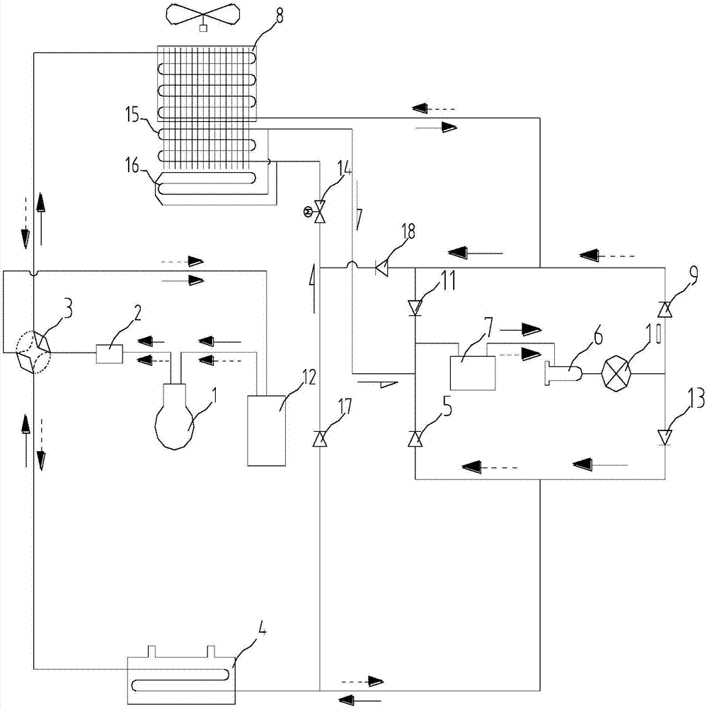
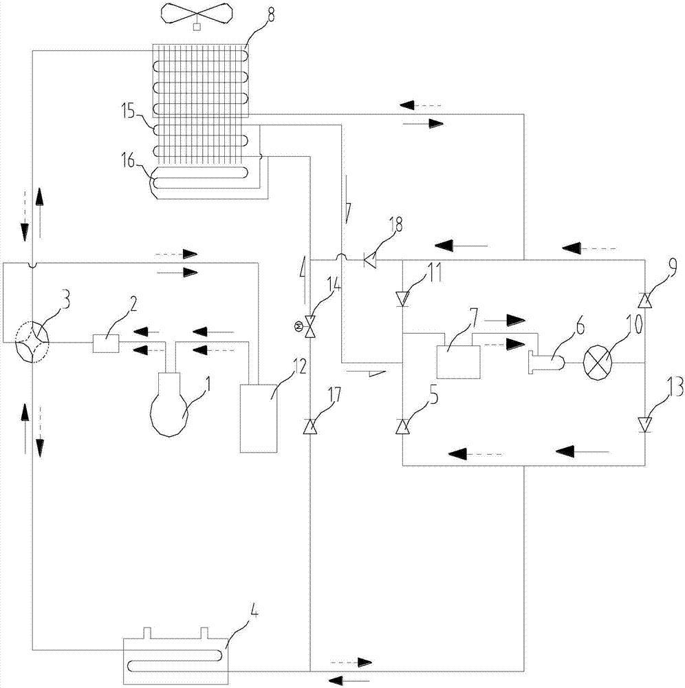
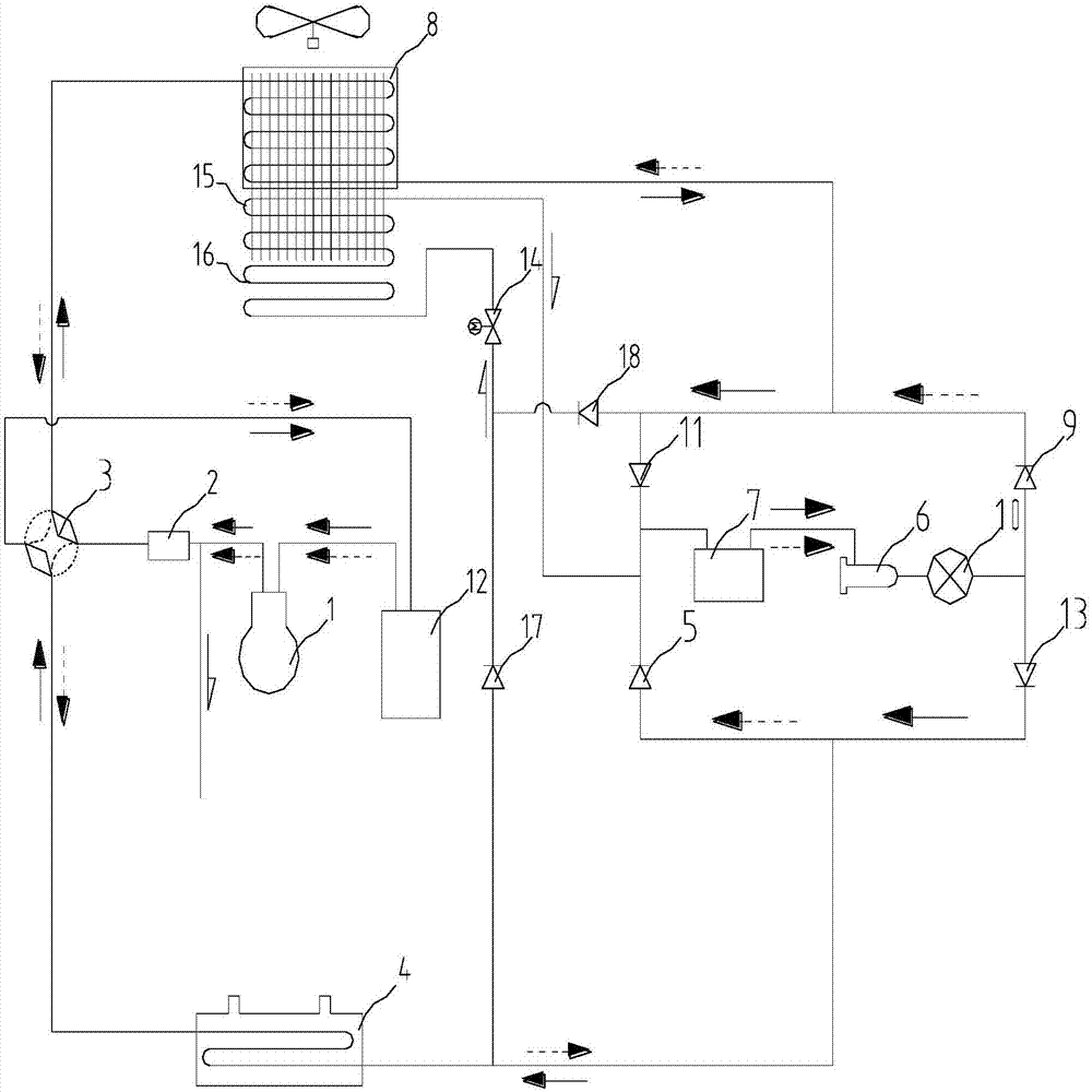
[0037] Please refer to Figure 1-Figure 3 , figure 1 A schematic diagram of the first embodiment of the heat pump unit provided by the present invention; figure 2 A schematic diagram of the second embodiment of the heat pump unit provided by the present invention; image 3 It is a schematic diagram of the third embodiment of the heat pump unit provided by the present invention.

[0038] Such as Figure 1-3 As shown, the heat pump unit is usually equipped with a compressor 1, a heat recovery device 2, a four-way valve 3, a first heat exchange part 4, a first one-way valve 5, a dry filter 6, a liquid reservoir 7, and a second heat exchange unit. Section 8, second one-way valve 9, expansion valve 10, third one-way valve...


PUM


Abstract

The invention discloses a heat pump unit, which comprises a first heat exchange part used as a condenser in a heating mode, a second heat exchange part used as an evaporator in a heating mode, an expansion valve and a water tray; The heat pump unit also includes a defroster arranged in the second heat exchange part, the defroster includes an inlet end and an outlet end; the inlet end of the defroster is connected to the outlet pipe section of the first heat exchange part and the second heat exchange part. Outlet pipe segment. The heat pump unit also includes an ice breaker arranged on the water tray, and the ice breaker also includes an inlet end and an outlet end; the inlet end of the ice breaker is also connected to the outlet pipe section of the first heat exchange part and the outlet pipe section of the second heat exchange part. In the heating mode, the defroster and the ice breaker are heated by the refrigeration medium flowing out from the first heat exchange part, and the defroster and the ice breaker are heated by the refrigeration medium flowing out from the second heat exchange part in the cooling mode. , so that the second heat exchange part and the water tray can be completely defrosted and ice broken, and the energy consumption of the heat pump unit will not be increased.

Description

technical field [0001] The invention relates to the technical field of heat pumps, in particular to a heat pump unit. Background technique [0002] Because the heat pump unit has the characteristics of low operating cost, energy saving, environmental protection and high energy efficiency during operation, it has been used more and more widely. For example, the heating and cooling air conditioners used in daily life and the air-cooled units used in industrial production are heat pump units. . [0003] During the working process of the heat pump unit, in the heating mode, there is a problem of frosting or even freezing of the evaporator and the problem of freezing of the water tray below the evaporator. [0004] Frosting and icing in the heating mode largely depend on the ambient temperature. When the ambient temperature drops below 10°, the body temperature of the evaporator will usually drop below 0° when the performance of the evaporator is satisfied, making the air The m...

Claims


Application Information

Patent Timeline
Patent Type & Authority Applications(China)
IPC IPC(8): F25B30/02F25B47/02F25B49/02
CPCF25B30/02F25B47/022F25B49/02F25B2700/21
Inventor 李一博
Owner HANRUN UNITED HIGH TECH DEV BEIJING CO LTD
Why Eureka
Try Eureka