Optical module and optical device state monitoring system

A state monitoring and optical device technology, applied in optical instrument testing, machine/structural component testing, instruments, etc., can solve the problems of high cost, long query or scanning time, low communication rate, etc., to achieve fast communication speed, reduce Cost, easy operation effect

Inactive Publication Date: 2018-04-27
DONGGUAN MENTECH OPTICAL & MAGNETIC CO LTD
View PDF4 Cites 12 Cited by
  • Summary
  • Abstract
  • Description
  • Claims
  • Application Information

AI Technical Summary

Problems solved by technology

[0003] In the prior art, optical module and optical device manufacturers generally adopt USB or I2C communication channel switching technology, which can realize the simultaneous communication between one host and hundreds of optical modules, optical devices, and optical devices, but it is difficult to solve the problem of It is difficult for one host to communicate with hundreds of thousands of optical modules, optical devices, and optical devices at the same time. If multiple hosts are used for monitoring, the cost of the entire test s...

Method used


Image

  • Optical module and optical device state monitoring system
  • Optical module and optical device state monitoring system
  • Optical module and optical device state monitoring system

Examples


Embodiment approach

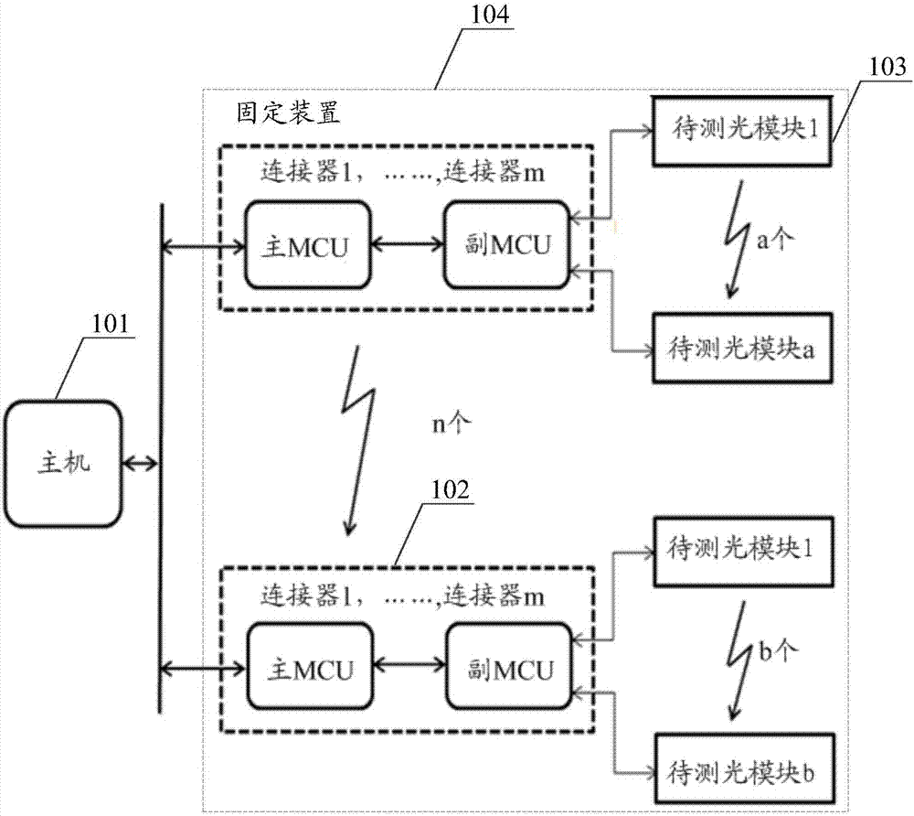
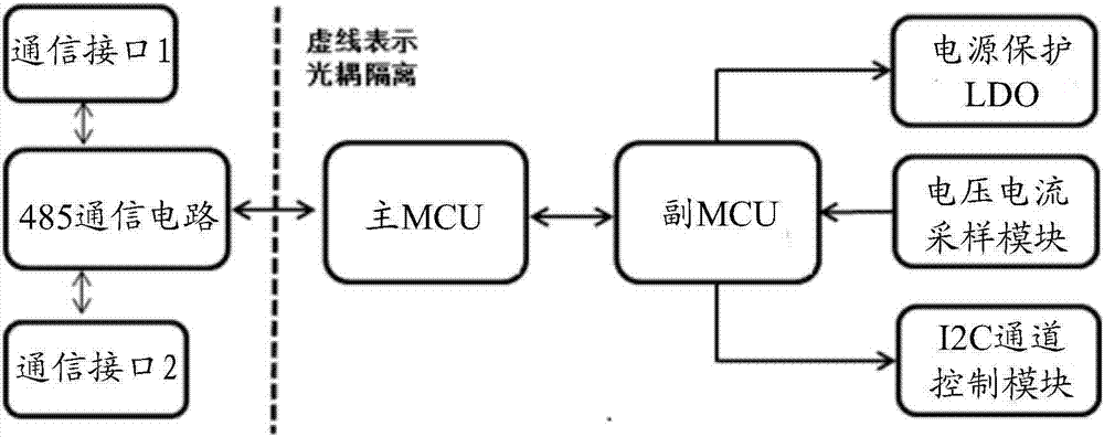
[0046] In a specific implementation manner, the circuit block diagram of the test board 102 is as follows figure 2 As shown, each test board uses a 485 communication circuit, including a main MCU, a sub-MCU, two RJ45 communication interfaces with electrical isolation, power supply protection low dropout linear regulator (power supply protection LDO), voltage and current sampling module, I2C Channel control module, Pin1 and 2 are Vcc+5V, Pin2 and 3 are A+, Pin4 and 5 are B-, Pin7 and 8 are ground. The main MCU and the sub-MCU use the I2C communication mechanism. The communication interface is a twisted pair insertion interface inside the network. The main / sub-MCU will monitor the working current of the modules on the test board in real time. The monitoring circuit can use high-precision sampling resistors and amplifiers to realize small current monitoring and stable monitoring data. The monitoring circuit is simple to implement and low in price, which greatly reduces the over...


PUM


Abstract

The embodiment of the invention discloses an optical module and optical device state monitoring system, an optical module and optical device temperature cycling test system and an optical module and optical device aging test system. The optical module and optical device state monitoring system comprises a main engine, test boards, to-be-tested optical modules or optical devices and fixing devices,wherein the main engine is connected with each test board through two twisted pairs respectively to form an RS485 bus network, and a communication protocol with an address and a fixed byte length isadopted for communication; each test board comprises a main MCU, an auxiliary MCU and a connector, the main MCU is used for networking communication with the main engine, and the auxiliary MCU is usedfor testing and monitoring performance parameters of the to-be-tested optical modules or optical devices and performing communication; each test board is connected with the to-be-tested optical modules or optical devices; and the test boards are in parallel connection, and together with the main engine, a bus network is formed. The working states of a large amount of optical modules or optical devices can be monitored in real time through controlling one main engine, and the construction cost, the maintenance cost and the use cost of the monitoring system are reduced.

Description

technical field [0001] Embodiments of the present invention relate to the technical field of manufacturing and testing of optical modules and optical devices, and in particular to a state monitoring system for optical modules and optical devices, a temperature cycle testing system for optical modules and optical devices, and an aging testing system for optical modules and optical devices. Background technique [0002] With the development of optical communication technology, the demand for optical modules and optical devices in the market is increasing. Low cost and high quality are people's constant pursuit, which forces optical communication component manufacturers to continuously improve their processes to Manufacture a large number of high-quality, low-cost optical modules and optical devices. Correspondingly, it is necessary to design and manufacture equipment for aging and temperature cycle testing that can simultaneously monitor the working status of a large number of...

Claims


Application Information

Patent Timeline
IPC IPC(8): G01M11/00H04B10/27
CPCG01M11/00H04B10/27
Inventor 周忠山刘小煜敬良才黄首甲张宏斌谢家宝田勇黄安珠
Owner DONGGUAN MENTECH OPTICAL & MAGNETIC CO LTD
Why Eureka
Try Eureka