Structure for heat radiation of battery module and installation and fixation of electrical cores

A battery module and fixed structure technology, applied in battery pack components, secondary batteries, structural parts, etc., can solve the problems of large volume, high energy consumption and high cost of the support frame, improve heat dissipation efficiency, and ensure reliability. , the effect of convenient operation

Inactive Publication Date: 2018-04-27
ANHUI OFFNENBACH NEW ENERGY TECH CO LTD
View PDF11 Cites 4 Cited by
  • Summary
  • Abstract
  • Description
  • Claims
  • Application Information

AI Technical Summary

Problems solved by technology

The existing battery modules usually have the following problems: 1. The plastic supporting frame itself is variable, and the battery cells and the supporting frame at the bottom of the battery module are due to the gravity of the upper battery module structure, and the lower battery module The structure of the group is easily deformed, which will lead to disordered contact between the tabs at both ends of the battery cell and the electrode plate, resulting in failure
2. The thick plastic support frame directly makes the weight of the module larger, so that more power is required for loading and use, which consumes a lot of energy
3. The thick plastic support frame is bulky and takes up more space, which is not conducive to its own assembly in the battery box and is not conducive to the assembly of the battery box on the vehicle
[0004] Existing battery modules mainly include battery cells and a support frame supporting the battery cells. Since the battery cells themselves generate a large amount of heat during use or charging of the battery modules, the heat dissipation of the battery modules is extremely severe. Importantly, in the prior art, a cooling module is generally installed on the battery module to realize heat dissipation during the use of the battery module. Setting the cooling module in the battery module not only costs a lot, but also makes the battery module more compact. Big

Method used


Image

  • Structure for heat radiation of battery module and installation and fixation of electrical cores
  • Structure for heat radiation of battery module and installation and fixation of electrical cores
  • Structure for heat radiation of battery module and installation and fixation of electrical cores

Examples


Embodiment Construction

[0026] combine Figure 1 to Figure 12 , the present invention is further described:

[0027] Combined with the structure of the entire battery module, the heat dissipation installation and fixing structure of the battery cell used for the battery module is described in detail below:

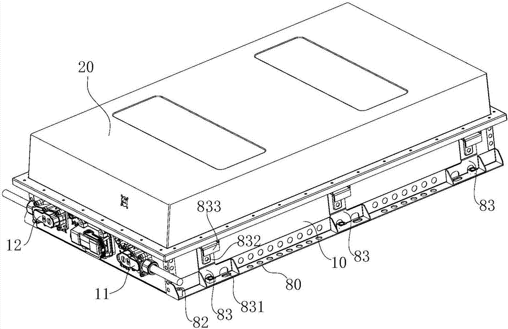
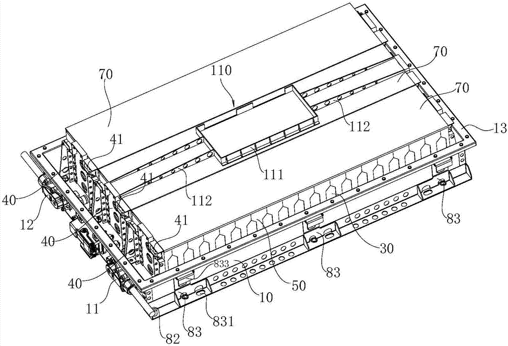
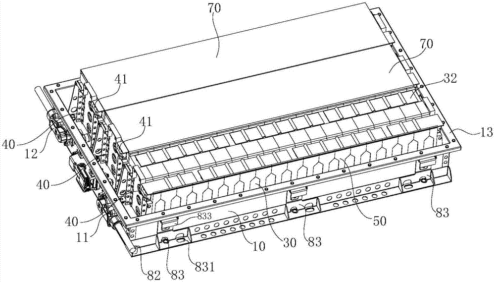
[0028] The battery module includes a bottom support 10 for installing the battery module. The bottom support 10 has an open box-like structure, and the side walls of the bottom support 10 are respectively provided with a module negative terminal 11 and a module positive connection terminal 12. The opening of the bottom bracket 10 is provided with a box cover 20. The battery module includes a plurality of battery packs arranged in parallel. The battery cell 30 located at the outermost side of the battery pack is provided with a supporting frame 40, and a locking screw 41 is arranged between the supporting frames 40 on both sides of the battery pack, and the locking screw 41 is parallel to the len...


PUM


Abstract

The invention relates to a structure for heat radiation of a battery module and installation and fixation of electrical cores. The structure comprises a bottom support which is in the structure of anopen-ended case; the battery module comprises a plurality of batteries arranged in parallel; two sides of the batteries are provided with bracing frames; locking screws are arranged between the bracing frames at two sides of the batteries; an isolation framework is arranged between every two adjacent electrical cores; the coupling ends of the bracing frames and the bottom support are provided withstrip-like trough plates; the lower plate surface of the bottom support is provided with a heat radiation plate; the edge of the heat radiation plate is provided with installing holes used for fixation with the chassis of an automobile; and second isolation frameworks are arranged between the bracing frames and the electrical cores. According to the invention, the lower plate surface of the bottom support of the battery module is provided with the heat radiation plate which can improve the heat radiation efficiency of the battery module; second installing holes in the connecting trough platesfacilitate insertion of a socket wrench into the second installing holes for connection with fastening bolts, so the fastening bolts can be tightly screwed, and operation is convenient; and the structure can ensure the firmness of electrical core installation.

Description

technical field [0001] The invention relates to the technical field of power batteries for new energy vehicles, in particular to a heat dissipation installation and fixing structure for battery cells used in battery modules. Background technique [0002] Battery modules are the "heart" of electric vehicles. The battery module is the core part of providing power energy for new energy vehicles such as electric vehicles and hybrid vehicles. It can be understood that battery cells are combined in series and parallel, and a battery monitoring and management device (MCN) is installed to manage and control them. The structural design of the battery module can often determine the performance and safety of a battery box. Its structure must support, fix and protect the battery cells. At the same time, how to meet the requirements of overcurrent, current uniformity, how to meet the control of battery cell temperature, and whether to cut off the power when there is a serious abnormal...

Claims


Application Information

Patent Timeline
Patent Type & Authority Applications(China)
IPC IPC(8): H01M10/613H01M10/625H01M10/6554H01M2/10H01M50/249
CPCH01M10/613H01M10/625H01M10/6554H01M50/20Y02E60/10
Inventor 曹杰
Owner ANHUI OFFNENBACH NEW ENERGY TECH CO LTD
Why Eureka
Try Eureka