
Pipeline switching device, washing machine water returning and draining switching method and washing machine

A pipeline switching and washing machine technology, applied in the field of washing machines, can solve the problems of easy failure, waste of washing water, high cost, etc., and achieve the effects of accelerating detergent dissolution, avoiding dandruff clogging, and reducing production costs

Active Publication Date: 2018-05-01
WUXI LITTLE SWAN ELECTRIC CO LTD
View PDF7 Cites 0 Cited by
  • Summary
  • Abstract
  • Description
  • Claims
  • Application Information

AI Technical Summary

Problems solved by technology

[0004] Although the above-mentioned methods can realize the backflow of drainage, there will be some shortcomings in actual use. Since it is necessary to use a special drainage pump with an additional backflow pump or set a reversing device inside the drainage pump, such a backflow method The cost is high, the structure is complex, and it is prone to failure. For example, when a reversing device such as a reversing vane is installed inside the drainage pump, the reversing device is usually relatively fine due to the limited internal space of the drainage pump, which is easy to cause Fur piles up to block or make the reversing device not tightly closed, so that part of the washing water is discharged to the outside of the washing machine during the process of draining and returning, resulting in waste of washing water, which is usually not easy to be noticed by users

Method used


Image

  • Pipeline switching device, washing machine water returning and draining switching method and washing machine
  • Pipeline switching device, washing machine water returning and draining switching method and washing machine
  • Pipeline switching device, washing machine water returning and draining switching method and washing machine

Examples


Embodiment Construction

[0038] Specific embodiments of the present invention will be described in detail below in conjunction with the accompanying drawings. It should be understood that the specific embodiments described here are only used to illustrate and explain the present invention, and are not intended to limit the present invention.

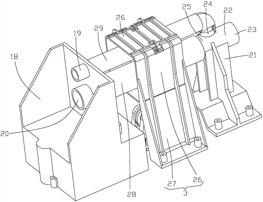
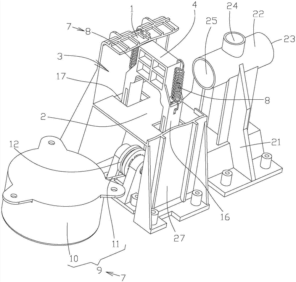
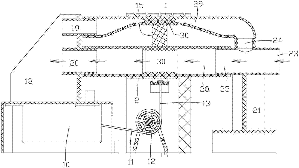
[0039] refer to Figure 1-6 As shown in the structure, the pipeline switching device provided by the present invention is used for fluid switching, so that the fluid can flow in a different direction. Specifically, the pipeline switching device includes a bracket 3 and a pipe clamp 4, wherein the bracket 3 includes spaced The first plate body 1 and the second plate body 2, the pipe clamp 4 is arranged between the first plate body 1 and the second plate body 2, and the first pipeline is formed between the pipe clamp 4 and the first plate body 1. Space 5, the second pipeline passes through the space 6 formed between the pipe clamp 4 and the second plate body 2, r...


PUM


Abstract

The invention relates to the technical field of washing machines, and discloses a pipeline switching device, a washing machine water returning and draining switching method and a washing machine. Thepipeline switching device comprises a support and a pipe clamp, the support comprises a first plate body and a second plate body which are arranged at an interval, the pipe clamp is arranged between the first plate body and the second plate body, a first pipeline through space and a second pipeline through space are formed among the first plate body, the second plate body and the pipe clamp, the pipe clamp can move to the first plate body under the action of external force, and the pipe clamp can move to the second plate body under the action of the external force. When the pipeline switchingdevice is applied in the washing machine, a special draining pump with a reflux pump in the prior art does not need to be arranged, washing water reflux can be achieved through an ordinary draining pump, water flow stirring in a washing cavity is achieved through the runback water so as to accelerate detergent dissolving, clothes rubbing is increased, contact with air is increased through water flow stirring, and the air content is correspondingly increased in water. The surface of the inner diameter of a water returning and draining pipeline of the washing machine can be kept smooth, blockingcaused by flock is avoided, and the production cost is lowered.

Description

technical field [0001] The invention relates to the technical field of washing machines, in particular to a pipeline switching device, a washing machine backwater switching method and a method. Background technique [0002] At present, with the improvement of people's quality of life, the penetration rate of washing machines is getting higher and higher. For example, washing machines on the market are mainly divided into two types: pulsator washing machines and drum washing machines. [0003] For example, in order to speed up the dissolution of detergent and increase the cleaning ratio, and reduce the wear on the surface of the clothes and the metal inner cylinder, the current drum washing machine usually uses the drain pump to drain and return, that is, the drain pump will be activated during the washing process. However, the drainage is not discharged, but is returned to the washing chamber through the return device after being discharged by the drainage pump, so as to in...

Claims


Application Information

Patent Timeline
Patent Type & Authority Applications(China)
IPC IPC(8): D06F39/08
CPCD06F39/081D06F39/083
Inventor 吴全红黄岩朱玮
Owner WUXI LITTLE SWAN ELECTRIC CO LTD
Learn More