Method and system for indicating characteristics of air intake systems under back pressure of hypersonic aircrafts

An air intake system, hypersonic technology, used in instruments, special data processing applications, electrical digital data processing, etc. Insufficient research on the flow and aerodynamic heating characteristics of the intake system

Inactive Publication Date: 2018-05-01
CHINA ACAD OF LAUNCH VEHICLE TECH
View PDF3 Cites 7 Cited by
  • Summary
  • Abstract
  • Description
  • Claims
  • Application Information

AI Technical Summary

Problems solved by technology

[0003] At present, domestic and foreign studies are mainly focused on the starting characteristics and anti-backpressure ability of the supersonic / hypersonic intake system under the action of back pressure, and there is no discussion on the impact of the shock position of the intake system on the intake system under the back pressure of the combustion chamber. The prediction of anti-backpressure performance of the system is inaccurate, and the forward transmission of the shock wave series leads to insufficient research on the flow and aerodynamic heating characteristics of the intake system, which leads to inaccurate prediction of the performance of the intake system and affects the design of the intake system

Method used


Image

  • Method and system for indicating characteristics of air intake systems under back pressure of hypersonic aircrafts
  • Method and system for indicating characteristics of air intake systems under back pressure of hypersonic aircrafts
  • Method and system for indicating characteristics of air intake systems under back pressure of hypersonic aircrafts

Examples


Embodiment

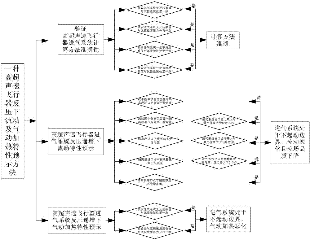
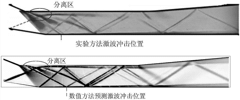
[0056] Next, the flow and aerodynamic heating characteristics of a hypersonic vehicle under the action of combustion chamber back pressure are calculated to analyze the effect of the method of the present invention.

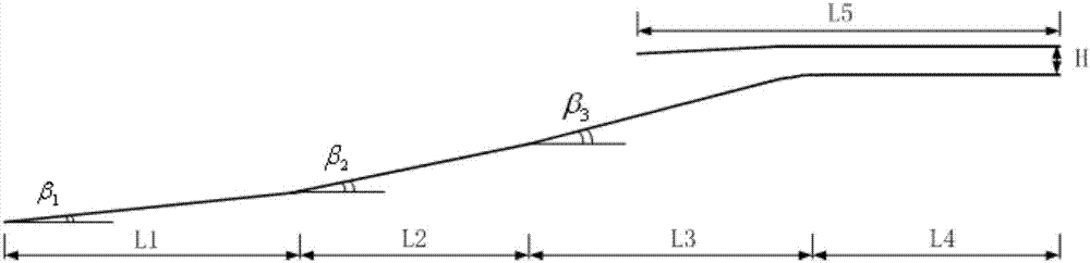
[0057] figure 2 As an example, the physical model of the air intake system of a hypersonic vehicle simulates the working state of a hypersonic engine with a flight Mach number Ma=6, simulates the wind tunnel conditions, and sets the far-field boundary conditions of the free flow pressure and the given back pressure of the combustion chamber inlet. Different multiples of incoming flow static pressure.

[0058] The two-dimensional coupled implicit NS equation and the RNGκ-ε turbulence model are used to simulate the flow field of the hypersonic engine intake system, and the standard wall function is used for processing. Considering that the total temperature of the free-flow air is low, it can be treated as an ideal gas. ICEM CFD software is used to generate grids...


PUM


Abstract

The invention discloses a method and system for indicating characteristics of air intake systems under back pressure of hypersonic aircrafts. The method comprises the following steps of: verifying thecorrectness of a hypersonic aircraft air intake system calculation method; simulating a hypersonic aircraft air intake system flow field to obtain air intake system schlieren figure under progressiveincrease of back pressure, judging an appointed range of distance between a shock wave forward pass position corresponding to each air intake schlieren figure and an inlet of an isolated section of the aircraft, and considering that the air intake systems are located in a non-starting boundary; and simulating the hypersonic aircraft air intake system flow field to obtain air intake system upper wall surface heat flow distribution figures under progressive increase of back pressure, judging an upper wall surface heat flow value of the inlet point at the isolated section according to each air intake system upper wall surface heat flow distribution figure, and if the upper wall surface heat flow value is greater than an appointed value, considering that the air intake systems are located inthe non-starting boundary and aerodynamic heating degrades. According to the method and system, back pressure preventing performance of the air intake systems can be pre-judged accurately, and designof the air intake systems is improved.

Description

technical field [0001] The invention belongs to the technical field of hypersonic aircraft, and in particular relates to a method and system for predicting characteristics of an intake system of a hypersonic aircraft under back pressure. Background technique [0002] A hypersonic engine (take the scramjet engine as an example) is composed of an intake system (intake port, isolation section), a combustion chamber, and an exhaust nozzle. The isolation section is an important part for dual-mode scramjet to realize dual-mode and mode conversion. At the same time, it isolates the intake port from the combustion chamber, prevents the high back pressure of combustion from affecting the intake port, and can provide a relatively wide working range for the intake port. Many factors affect the start position, strength and performance of the intake system of the shock train, and the back pressure of the combustion chamber is one of the factors that must be considered. In addition, the...

Claims


Application Information

Patent Timeline
Patent Type & Authority Applications(China)
IPC IPC(8): G06F17/50
CPCG06F30/15G06F30/20Y02T90/00
Inventor 张升升杨旸费王华王兆伟张永郑思行吕雅江凌彤
Owner CHINA ACAD OF LAUNCH VEHICLE TECH
Why Eureka
Try Eureka