Arc light protection type automatic pressure relief device

A pressure relief device and automatic protection technology, applied in the direction of switchgear, switchgear setting, electrical components, etc., can solve the problems of the deformation of the switchgear cabinet, the threat to the personal safety of nearby personnel, etc., and achieve the effect of ensuring integrity

Pending Publication Date: 2018-05-01
SHANGHAI BAOLIN ELECTRIC GRP
View PDF0 Cites 8 Cited by
  • Summary
  • Abstract
  • Description
  • Claims
  • Application Information

AI Technical Summary

Problems solved by technology

This pressure relief device can easily cause serious deformation of the swi

Method used


Image

  • Arc light protection type automatic pressure relief device
  • Arc light protection type automatic pressure relief device
  • Arc light protection type automatic pressure relief device

Examples


Embodiment Construction

[0025] The following will clearly and completely describe the technical solutions in the embodiments of the present invention with reference to the accompanying drawings in the embodiments of the present invention. Obviously, the described embodiments are only some, not all, embodiments of the present invention. Based on the embodiments of the present invention, all other embodiments obtained by persons of ordinary skill in the art without making creative efforts belong to the protection scope of the present invention.

[0026] In order to make the above objects, features and advantages of the present invention more comprehensible, the present invention will be further described in detail below in conjunction with the accompanying drawings and specific embodiments.

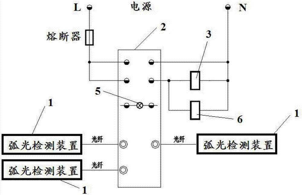
[0027] figure 1 It is a circuit structure diagram of an embodiment of an automatic pressure relief device for arc protection in the present invention.

[0028] see figure 1 , The arc protection automatic pressur...


PUM


Abstract

The invention discloses an arc light protection type automatic pressure relief device. The automatic pressure relief device comprises arc light detection devices, a control device, a pressure relief switch and a pressure relief cover, wherein each arc light detection device is mounted in each electrical room of a switch cabinet, and output ends of the arc light detection devices are electrically connected with the control device; the output end of the control device is electrically connected with the pressure relief switch; a pressure relief hole is formed in the top of the switch cabinet, andthe pressure relief cover covers the pressure relief hole and is hinged with the switch cabinet; and the pressure relief switch is located at the joint of the pressure relief cover and the switch cabinet, is fixed on the switch cabinet, is connected with the pressure relief cover and is used for opening the pressure relief cover. By utilizing the arc light protection type automatic pressure relief device, the completeness of a cabinet body of the switch cabinet and the personal safety of nearby people can be guaranteed.

Description

technical field [0001] The invention relates to the technical field of electrical protection, in particular to an automatic pressure relief device for arc protection. Background technique [0002] When a fault occurs inside the switchgear, it is easy to generate an arc. When an arc is generated, after the arc is generated inside the switch cabinet, the change process inside the cabinet may go through the following four stages: [0003] 1. Compression stage: the electric arc occupies the entire air space, and the overheated temperature is generated due to the continuous release of energy. Under the air exchange of convection and radiation, the air remaining in the switch cabinet is heated, resulting in temperature values ​​and pressures in different areas The values ​​are not the same. [0004] 2. Expansion stage: From the moment of entering the expansion stage, the internal pressure of the switchgear increases until it reaches the maximum value, and then begins to decrease...

Claims


Application Information

Patent Timeline
IPC IPC(8): H02B13/025
CPCH02B13/025
Inventor 马志强徐红卫胡强包莉达
Owner SHANGHAI BAOLIN ELECTRIC GRP
Why Eureka
Try Eureka