Optical network unit loop detection method and device

An optical network unit and loop detection technology, applied in the field of passive optical network and Ethernet, can solve problems such as affecting other users' normal services, EPON system paralysis, network congestion, etc., to achieve the effect of improving loop detection efficiency

Active Publication Date: 2018-05-01
LUSTER TERABAND PHOTONICS TECHNOLOGY CO LTD
View PDF4 Cites 1 Cited by
  • Summary
  • Abstract
  • Description
  • Claims
  • Application Information

AI Technical Summary

Problems solved by technology

The loop will cause broadcast, multicast, unknown unicast flooding in the EPON system, and mac (Media Access Control, physical address) drift of normal business, etc., which will not only cause network congestion, but also affect the normal business of a large number of other users. It may even cause the EPON system to be paralyzed

Method used


Image

  • Optical network unit loop detection method and device
  • Optical network unit loop detection method and device
  • Optical network unit loop detection method and device

Examples


Embodiment Construction

[0062] The following will clearly and completely describe the technical solutions in the embodiments of the present invention with reference to the accompanying drawings in the embodiments of the present invention. Obviously, the described embodiments are part of the embodiments of the present invention, not all of them. Based on the embodiments of the present invention, all other embodiments obtained by persons of ordinary skill in the art without creative efforts fall within the protection scope of the present invention.

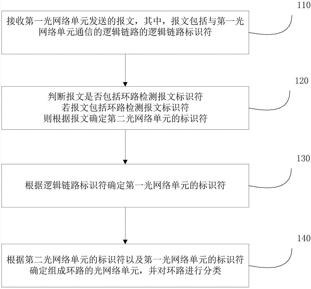
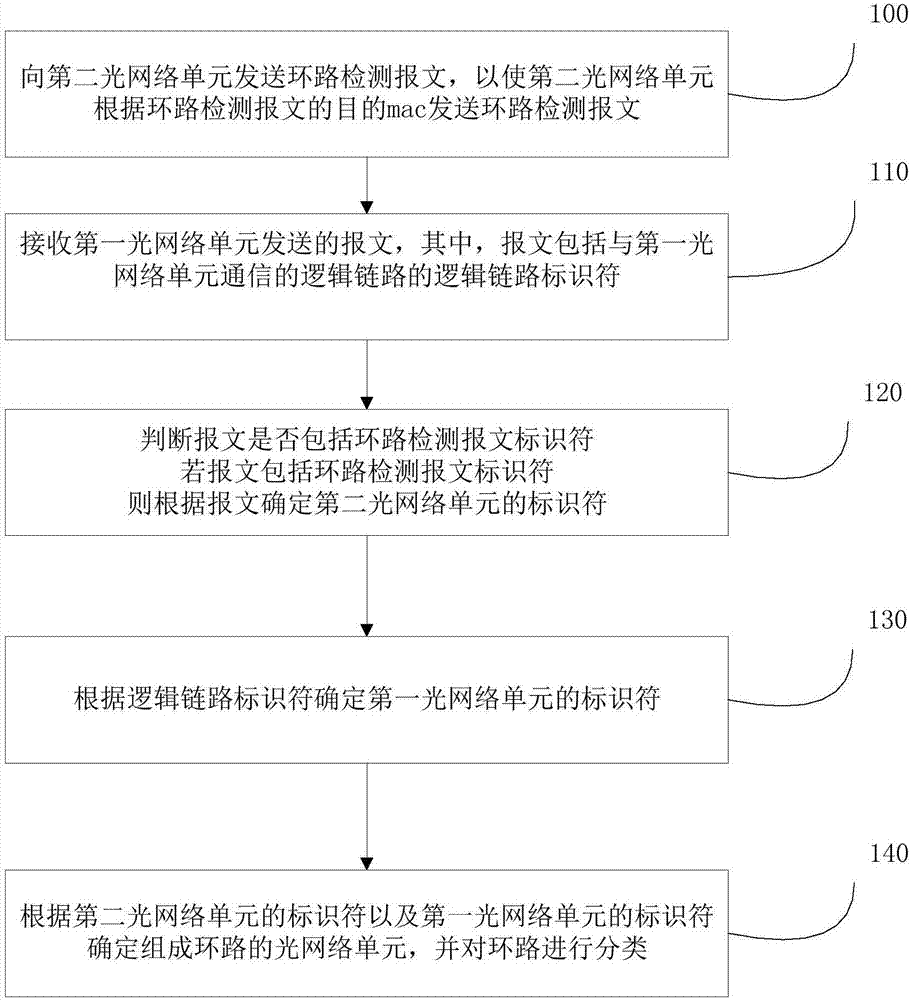
[0063] A kind of optical network unit loop detection method, such as figure 2 As shown, the method includes the following steps:

[0064] 110. Receive a packet sent by the first optical network unit, where the packet includes a logical link identifier of a logical link communicating with the first optical network unit;

[0065] It should be noted that this step and the ONU loop detection method in the embodiment of the present invention are executed by t...


PUM


Abstract

An embodiment of the invention provides an optical network unit loop detection method and device. The method includes the steps: firstly, judging whether a message transmitted from a first optical network unit and received by a passive optical network interface board is a loop detection message or not, and determining an identifier of a second optical network unit according to contents of the message if the message is the loop detection message; secondly, determining an identifier of a first optical network unit according to a logical link identifier of communication of the passive optical network interface board and the first optical network unit; finally, determining optical network units forming loops according to the identifier of the second optical network unit the identifier of the first optical network unit, and performing classification on the loops. By the aid of the technical scheme, the identifiers of the optical network units are set in the loop detection message, query ofan mac (media access control) table is avoided when the loops are detected, so that loops in an EPON (Ethernet passive optical network) system can be rapidly detected, normal operation of the EPON system is ensured, and normal network services are provided for users.

Description

technical field [0001] Embodiments of the present invention relate to the technical field of passive optical network and Ethernet, and more specifically, to a method and device for detecting an optical network unit loop. Background technique [0002] EPON (Ethernet Passive Optical Network, Ethernet Passive Optical Network) is an Ethernet-based passive optical network technology. It adopts a point-to-multipoint structure, uses passive optical fiber for data transmission, provides users with various business services on Ethernet, and combines the advantages of PON (passive optical network) technology and Ethernet technology. Such as figure 1 As shown, the EPON system is composed of a central office equipment OLT (Optical Line Terminal, Optical Line Terminal), a user equipment ONU (Optical Network Unit, Optical Network Unit) and an Optical Distribution Network (ODN, Optical Distribution Network). The OLT is used to connect the main optical fiber equipment, the ONU is used to ...

Claims


Application Information

Patent Timeline
Patent Type & Authority Applications(China)
IPC IPC(8): H04B10/077H04B10/275H04Q11/00
CPCH04B10/077H04B10/0773H04B10/275H04Q11/0067
Inventor 王磊姚毅
Owner LUSTER TERABAND PHOTONICS TECHNOLOGY CO LTD
Why Eureka
Try Eureka