Water tank circuit of cleaning device, cleaning device and cleaning device water tank control method

A technology for cleaning devices and water tanks, which is applied in cleaning action control, cleaning equipment, cleaning machinery, etc., can solve problems such as water tank control, and achieve the effects of cost saving, responsiveness, and increased intelligence

Pending Publication Date: 2018-05-04
GUANGDONG BONA ROBOT CORP LTD
View PDF5 Cites 8 Cited by
  • Summary
  • Abstract
  • Description
  • Claims
  • Application Information

AI Technical Summary

Problems solved by technology

[0005] The embodiment of the present invention provides a water tank circuit of a cleaning device, which solves the problem of water tank control in the prior art

Method used


Image

  • Water tank circuit of cleaning device, cleaning device and cleaning device water tank control method
  • Water tank circuit of cleaning device, cleaning device and cleaning device water tank control method
  • Water tank circuit of cleaning device, cleaning device and cleaning device water tank control method

Examples


Embodiment 1

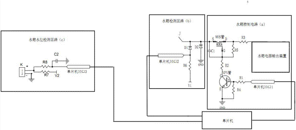
[0045] Such as figure 1 As shown, the present application provides a cleaning device water tank circuit, the water tank circuit includes a water tank control circuit a, which can control the power supply to the water pump or cut off the power to achieve the purpose of making the cleaning device mop the floor or stop mopping the floor, and intelligently control the water tank of the cleaning device the goal of.

[0046] A water tank circuit of a cleaning device, the water tank circuit includes a water tank control circuit, and the water tank control circuit includes a single-chip microcomputer, an NPN tube, a MOS tube, a resistor R1, a resistor R2, a resistor R3, a water tank power output device, and a water pump interface J.

[0047] Among them, the NPN tube belongs to the prior art and includes three electrodes, one common electrode becomes the base B of the triode, and the other two electrodes are called electrode C and electrode E. The function of NPN is to play the role o...

Embodiment 2

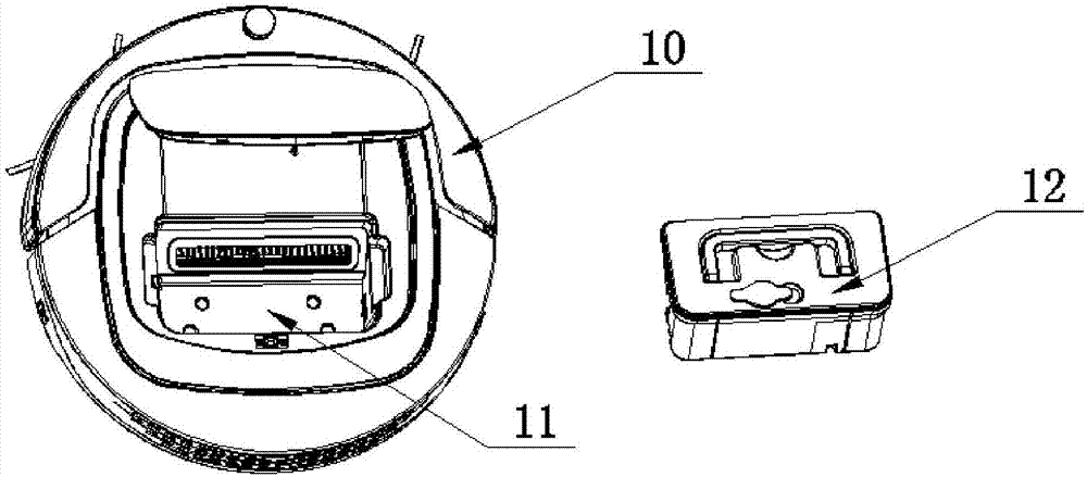
[0062] Such as figure 2 As shown, the present application provides a cleaning device, which includes a body 10 and a water tank 12 . The body 10 is provided with an accommodating space 11 , and the water tank 12 can be selectively placed in the vacant space 11 . The cleaning device contains the water tank circuit described in any one of the first embodiments of the invention.

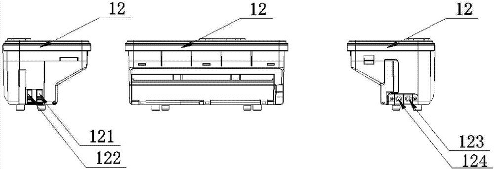
[0063] Such as Figure 3-Figure 5 As shown, the water tank 12 includes a water tank pump (not shown), and a liquid diffuser (not shown). The water tank water pump is sealed and waterproofed, and is arranged in the water tank 12 inside. One side of the water tank 12 is provided with a conductive shrapnel 121 and a conductive shrapnel 122 near the lower end of the water tank. The conductive shrapnel 121 and the conductive shrapnel 121 abut against the conductive contacts 111 and 112 in the empty space 11 to trigger the water tank detection circuit b. The side of the water tank 12 opposite to the condu...

Embodiment 3

[0067] Such as Figure 6 As shown, the present application provides a water tank control method of a cleaning device, and the method includes the following steps:

[0068] S1: the cleaning device detects whether the water tank is placed, if so, enters step S2; otherwise enters step S5;

[0069] S2: After detecting that the water tank is placed, the cleaning device detects whether there is water in the water tank, and if it detects that the water tank has water, then enters step S3; if it detects that the water tank has no water, then enters step S4;

[0070] S3: The single-chip microcomputer of the water tank circuit of the cleaning device inputs high voltage to the IO port (1) of the single-chip microcomputer to turn on the water pump, executes the action of mopping the floor, and returns to step S2 after a predetermined time;

[0071] S4: the single-chip microcomputer of the water tank circuit of the cleaning device inputs low voltage to the IO port (1) of the single-chip m...


PUM


Abstract

The invention provides a water tank circuit of a cleaning device. The water tank circuit comprises a water tank control circuit, the water tank control circuit comprises a single chip microcomputer, an NPN pipe, an MOS pipe, a resistor R1, a resistor R2, a resistor R3, a water tank power output device and a water pump interface (J), an IO opening (1) of the single chip microcomputer is connected with a B pole of the NPN pipe through the resistor R1, an E pole of the NPN pipe is grounded (GND), a C pole of the NPN pipe is connected to a G pole of the MOS pipe through the resistor R2, a D pole of the MOS pipe is connected to the power output device through the resistor R3, and an S pole of the MOS pipe is connected to the water pump interface (J). Through the water tank control circuit, a water tank water pump can be effectively started and closed, the reaction is sensitive, and the cost is greatly saved. Meanwhile, a water tank detection circuit and a water tank water level detection circuit are further arranged in the water tank control circuit, whether a water tank is placed and whether water is in the water tank or not can be quickly detected, and the intelligence of the cleaningdevice is improved. The invention further provides a water tank control method of the cleaning device.

Description

technical field [0001] The invention relates to a cleaning device, in particular to a water tank circuit of the cleaning device, a cleaning device and a control method for the water tank of the cleaning device. Background technique [0002] With the advancement of technology, cleaning devices are usually equipped with dust boxes and water tanks, which not only have the function of dust collection, but also can realize the function of mopping the floor. The water tank and the dust box can be integrated in the cleaning device, but the small capacity of the water tank results in a limited mopping area, and the user needs to add water several times to finish mopping the house, which increases the user's workload. [0003] Therefore, the prior art mostly adopts the separate type of water tank and dust box. The dust box and water tank are usually set with a micro switch to judge. If the placed device triggers the micro switch, the cleaning device judges that the placed device is ...

Claims


Application Information

Patent Timeline
Patent Type & Authority Applications(China)
IPC IPC(8): A47L11/28A47L11/40
CPCA47L11/28A47L11/4002A47L11/4011A47L11/4083A47L2201/06
Inventor 杨锴其他发明人请求不公开姓名
Owner GUANGDONG BONA ROBOT CORP LTD
Why Eureka
Try Eureka