Dynamic bias control circuit and Doherty power amplifier

A technology of power amplifier and bias control, which is applied in the direction of power amplifier, amplifier protection circuit layout, improving amplifier to improve efficiency, etc. It can solve the problems of DC power consumption, deterioration of back-off efficiency, and unsatisfactory equivalent impedance, etc., to achieve The effect of improving linearity

Pending Publication Date: 2022-04-08
MISIC MICROELECTRONICS CO LTD
View PDF0 Cites 0 Cited by
  • Summary
  • Abstract
  • Description
  • Claims
  • Application Information

AI Technical Summary

Problems solved by technology

The actual situation is that the auxiliary power amplifier biased in class C consumes a certain amount of DC power consumption in the fallback mode, and the equivalent impedance seen from the auxiliary power amplifier is not ideal, thus deteriorating the fallback efficiency

Method used


Image

  • Dynamic bias control circuit and Doherty power amplifier
  • Dynamic bias control circuit and Doherty power amplifier
  • Dynamic bias control circuit and Doherty power amplifier

Examples


Embodiment Construction

[0027] The following will clearly and completely describe the technical solutions in the embodiments of the present invention with reference to the accompanying drawings in the embodiments of the present invention. Obviously, the described embodiments are only some, not all, embodiments of the present invention. Based on the embodiments of the present invention, all other embodiments obtained by those skilled in the art without creative efforts fall within the protection scope of the present invention. In addition, it should be understood that the specific embodiments described here are only used to illustrate and explain the present invention, and are not intended to limit the present invention. In the present invention, unless stated otherwise, the used orientation words such as "up", "down", "left", and "right" usually refer to the upper, lower, left under the actual use or working state of the device. and right, specifically the direction of the drawing in the attached dra...


PUM


Abstract

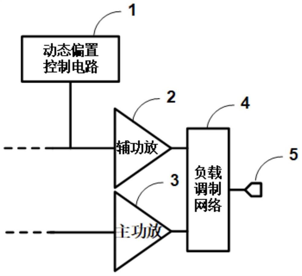
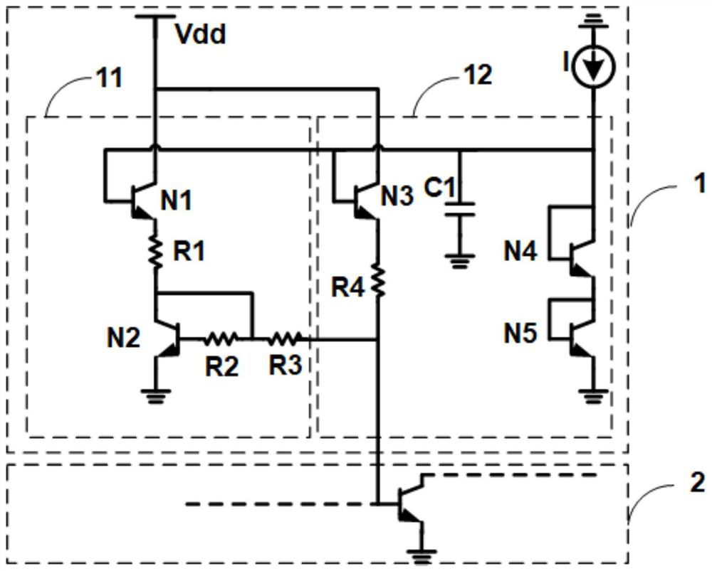
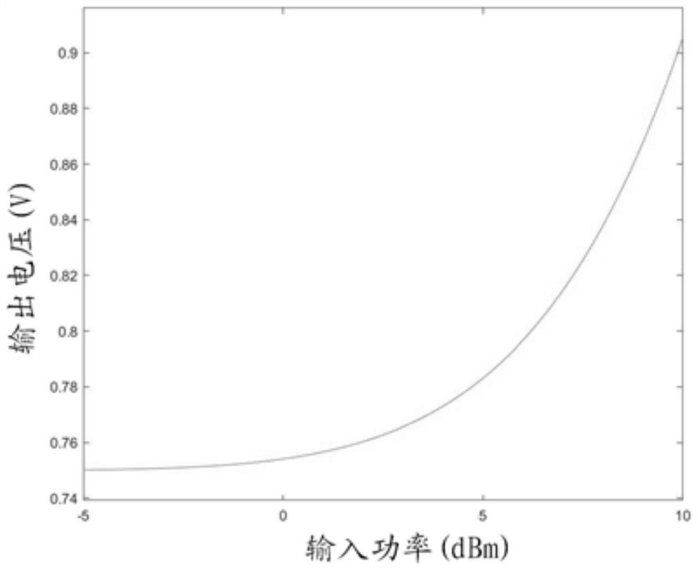
The invention discloses a dynamic bias control circuit and a Doherty power amplifier. The dynamic bias control circuit is used for the Doherty power amplifier and is electrically connected with an auxiliary power amplifier in the Doherty power amplifier, and the dynamic bias control circuit comprises a dynamic bias step-down circuit and a dynamic bias booster circuit; the output voltage of the dynamic bias step-down circuit is in negative correlation with the input power of the auxiliary power amplifier, and the output voltage of the dynamic bias step-up circuit is in positive correlation with the input power of the auxiliary power amplifier; the dynamic bias control circuit is used for correspondingly adjusting the bias voltage provided for the auxiliary power amplifier according to the output voltage of the dynamic bias step-down circuit and the dynamic bias step-up circuit so as to reduce the bias voltage to limit the power amplitude of the auxiliary power amplifier when the input power is larger than the first preset power. According to the scheme, the rollback efficiency can be improved, and the safety of the transistor of the auxiliary power amplifier in an over-high power mode is protected.

Description

technical field [0001] The invention relates to the technical field of power amplifiers, in particular to a dynamic bias control circuit and a Doherty power amplifier. Background technique [0002] As the last active circuit of the millimeter wave transmitter, the power amplifier is responsible for the efficiency, power, linearity and other indicators. Generally, the power consumption of a power amplifier (abbreviated as a power amplifier, hereinafter the same) accounts for more than half of the DC power consumption of the entire transmitter link. Therefore, efficiency is the key performance to measure the performance of a power amplifier. [0003] In order to improve the working efficiency of the power amplifier, many key technologies have emerged, such as: Kahn envelope separation and recovery technology, envelope tracking technology, Outphasing technology and Doherty technology. Among them, the Doherty technology uses the main power amplifier and the auxiliary power amp...

Claims


Application Information

Patent Timeline
IPC IPC(8): H03F1/02H03F1/32H03F1/52H03F3/21
Inventor 王龙向渝徐小杰
Owner MISIC MICROELECTRONICS CO LTD
Why Eureka
Try Eureka