Infrared-visible dual-band photoelectric detection system and optical axis deflection angle measurement method

A photoelectric detection, dual-band technology, applied in the optical field, can solve the problems of unusable, performance discount, difficult to observe, etc.

Inactive Publication Date: 2021-06-08
XIAN TECH UNIV
View PDF11 Cites 0 Cited by
  • Summary
  • Abstract
  • Description
  • Claims
  • Application Information

AI Technical Summary

Problems solved by technology

The dual-band optical system can perform multi-band detection on the measured object, and simultaneously detect the measured objects in different radiation bands, which is impossible for a single optical system
The dual-band optical system has the comprehensive advantages of visible light, infrared or ultraviolet optical system, but it is not a simple addition, such as a dual-band optical system combining visible light and mid-wave infrared light. Among them, the visible light band optical system is rich and diverse and mature. It can meet various design requirements, and visible light can be accepted by the human eye, so it is convenient to observe. However, the optical system in the visible light band requires a certain amount of light when used, and its performance is greatly reduced or even unusable at night and in low-light conditions. At the same time, it is susceptible to Environmental interference, it is difficult to observe when there is fog or occlusion

Method used


Image

  • Infrared-visible dual-band photoelectric detection system and optical axis deflection angle measurement method
  • Infrared-visible dual-band photoelectric detection system and optical axis deflection angle measurement method
  • Infrared-visible dual-band photoelectric detection system and optical axis deflection angle measurement method

Examples


Embodiment Construction

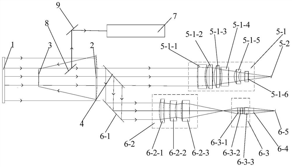
[0050] Such as figure 1 and figure 2 An infrared-visible dual-band photoelectric detection system shown includes a reflective system arranged on the reflected light path of the measured object 1, a beam splitter 4 for splitting the mid-wave infrared wave and the visible light wave, and a beam splitter located at the beam splitter 4. The visible light imaging unit on the optical path and the mid-wave infrared light imaging unit located on the reflection optical path of the spectroscope 4, and the optical axis deflection angle measurement unit located on the reflection optical path of the reflection system, the measured object 1 can simultaneously reflect the wave infrared and visible light.

[0051] During specific implementation, the reflective system reflects the visible light and mid-wave infrared light reflected by the measured object 1 into the beam splitter 4 as a parallel beam, and the beam splitter 4 transmits the visible light to the visible light imaging unit and re...


PUM

PropertyMeasurementUnit
refractive indexaaaaaaaaaa

Abstract

The invention discloses an infrared-visible dual-band photoelectric detection system and a method for measuring the deflection angle of the optical axis. The photoelectric detection system includes a reflection system, a beam splitter, a visible light imaging unit located on the reflection light path of the beam splitter, and a mid-wave infrared light imaging unit in the transmission light path unit, and the optical axis deflection angle measurement unit, the optical axis deflection angle measurement method includes: 1. Initialize the CCD sensor and obtain the background grayscale image; 2. Mid-wave infrared optical axis alignment; 3. Visible light spot imaging; 4. Visible light Acquisition of light spot images; 5. Acquisition of centroid coordinates of visible light spot images; 6. Calculation of optical axis declination. The invention combines the advantages of the visible light band optical system and the mid-wave infrared band optical system, improves the efficiency of observation and detection, realizes long-distance, high-resolution and all-weather imaging, and effectively improves the imaging quality, and the optical axis deflection angle measurement unit can measure visible light The deflection angle between the optical axis and the mid-wave infrared optical axis measures the stability of the entire photodetection system.

Description

technical field [0001] The invention belongs to the field of optical technology, and in particular relates to an infrared-visible dual-band photoelectric detection system and an optical axis deflection angle measurement method. Background technique [0002] With the improvement of social needs and the advancement of science and technology, higher and higher requirements are put forward for the performance of optical systems, especially in the field of detection and detection. Rapid and timely discovery of targets, real-time tracking and accurate measurement of targets have become optical systems. The mainstream trend of system development. [0003] In order to obtain more detection information and conduct comprehensive detection and precise observation of measured objects with different spectral characteristics, a dual-band and multi-band optical system has been developed. The dual-band optical system can perform multi-band detection of the measured object, and simultaneous...

Claims


Application Information

Patent Timeline
Patent Type & Authority Patents(China)
IPC IPC(8): G01S17/89G01S7/481G01M11/02G02B17/06G02B27/10H04N5/225H04N5/33H04N5/372H04N17/00
CPCH04N5/33H04N17/002G02B17/06G02B27/1006G01M11/00G01M11/0221G01S7/481G01S17/89H04N23/50H04N23/55H04N25/71
Inventor 于洵韩峰聂亮陶禹陈靖刘宝元路绍军张维光张祥伟马群尚小燕郭钰琳
Owner XIAN TECH UNIV
Why Eureka
Try Eureka