A remote monitoring system for medical equipment based on communication network
What is Al technical title?
Al technical title is built by PatSnap Al team. It summarizes the technical point description of the patent document.
A technology for remote monitoring systems and medical equipment, applied in mechanical equipment, closed-circuit television systems, components of television systems, etc., can solve the problems of wasting time and inconvenient installation.
Active Publication Date: 2019-11-08
广州景联信息科技有限公司
View PDF4 Cites 0 Cited by
Summary
Abstract
Description
Claims
Application Information
AI Technical Summary
This helps you quickly interpret patents by identifying the three key elements:
Problems solved by technology
Method used
Benefits of technology
Problems solved by technology
[0004] In view of the deficiencies in the prior art, the purpose of the present invention is to provide a remote monitoring system for medical equipment based on a communication network, so as to solve the problem that users need to drill holes for installation, which is inconvenient to install and requires professional installers to install, and Questions that waste a lot of time
Method used
Image
Click on the blue label to locate the original text in one second.
Reading with bidirectional positioning of images and text.
Examples
Embodiment Construction
[0023] In order to make the technical means, creative features, goals and effects achieved by the present invention easy to understand, the present invention will be further described below in conjunction with specific embodiments.
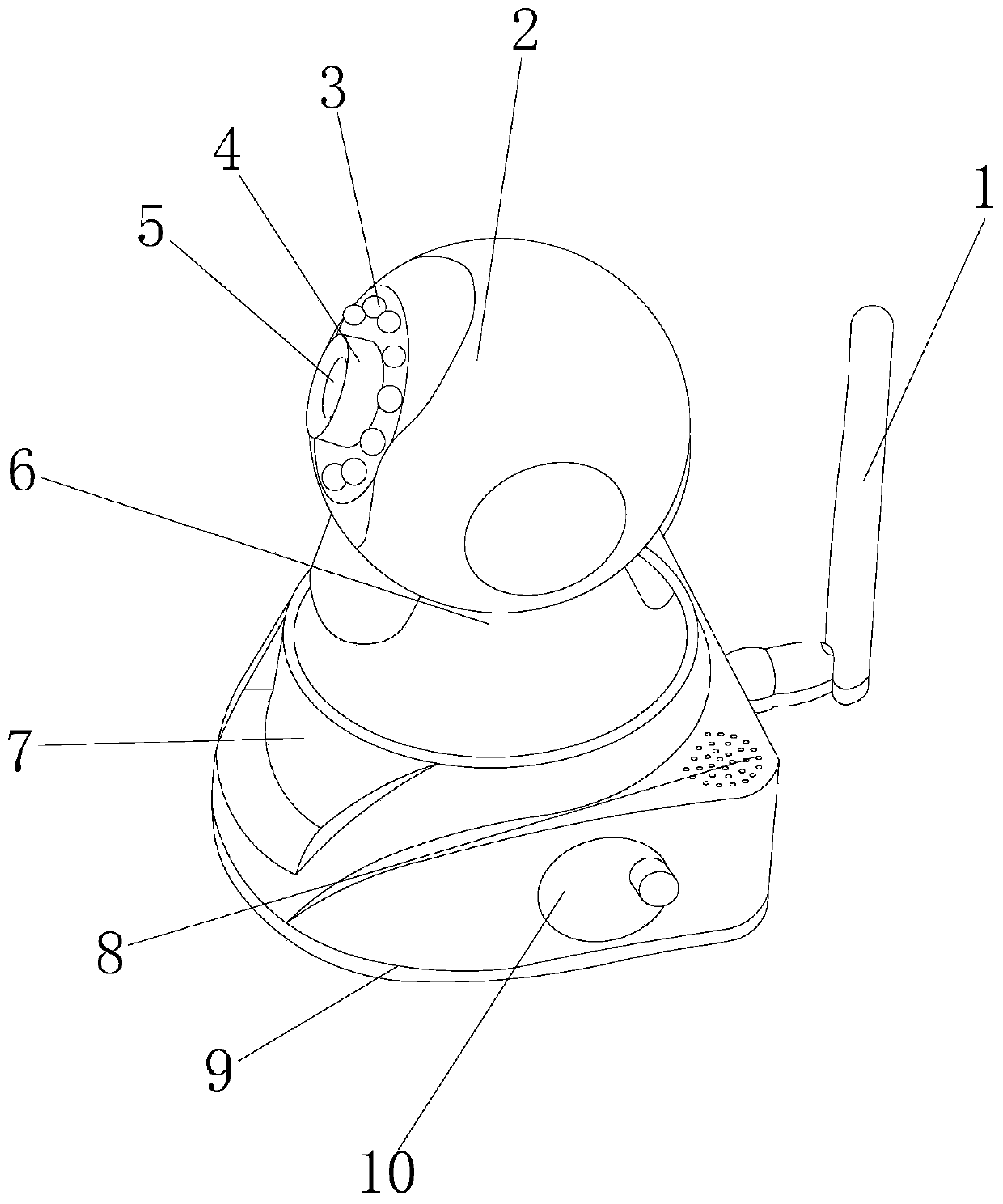
[0024] see Figure 1-Figure 5 , the present invention provides a technical solution of a remote monitoring system for medical equipment based on a communication network: its structure includes a communication signal pole 1, a monitoring eye shell 2, a night vision light 3, an automatic focus knob 4, a camera 5, a rotating disk 6, and a housing 7. Amplifying hole 8, fixed base 9, suction cup fixing mechanism 10, the communication signal rod 1 is installed on the rear end of the housing 7, and the top of the housing 7 is provided with a rotating disk 6;
[0025] The rotating disc 6 and the housing 7 adopt a clearance fit, the bottom of the housing 7 is provided with a fixed base 9, the fixed base 9 and the housing 7 are an integrated structure, and ...
PUM
Abstract
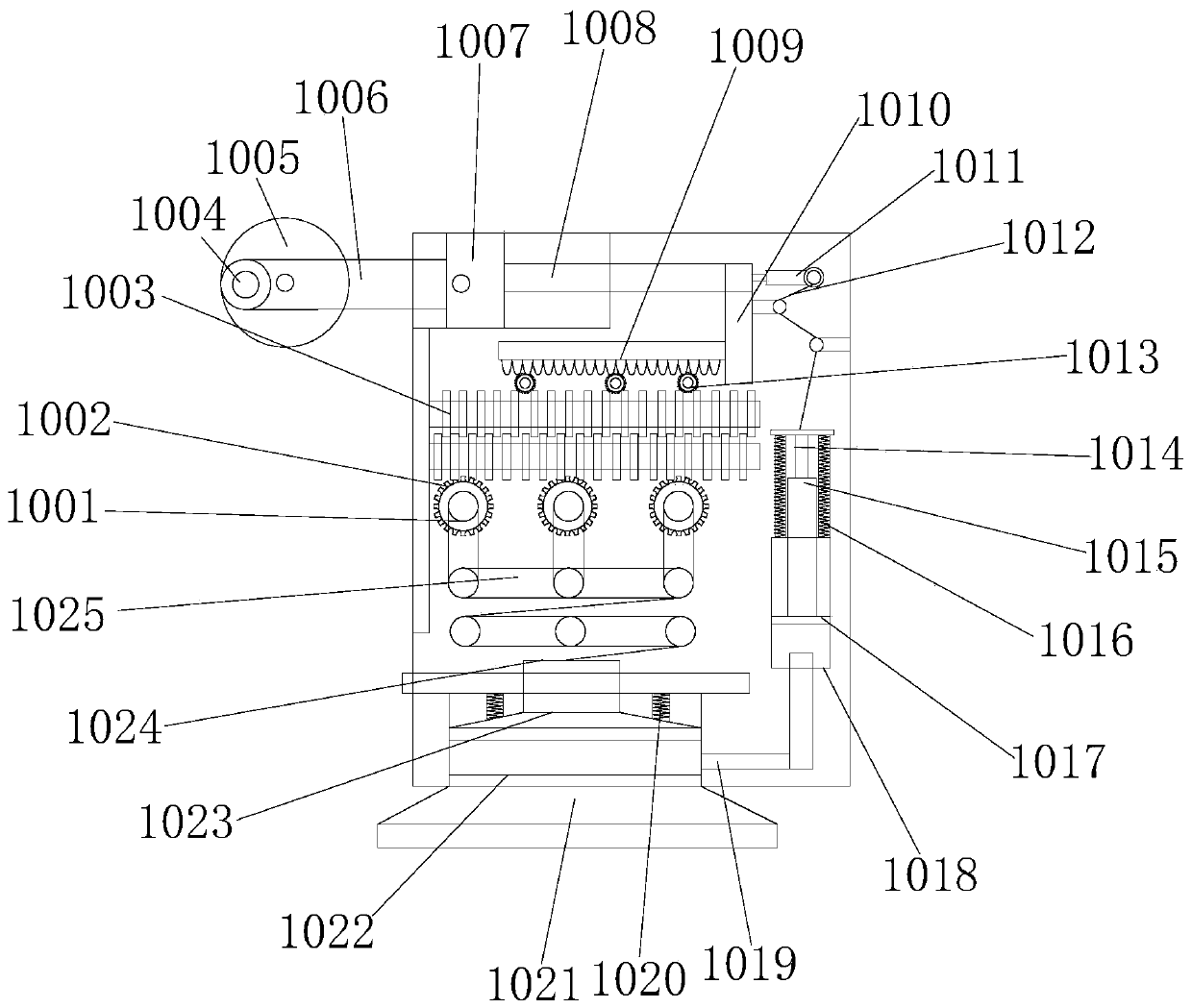
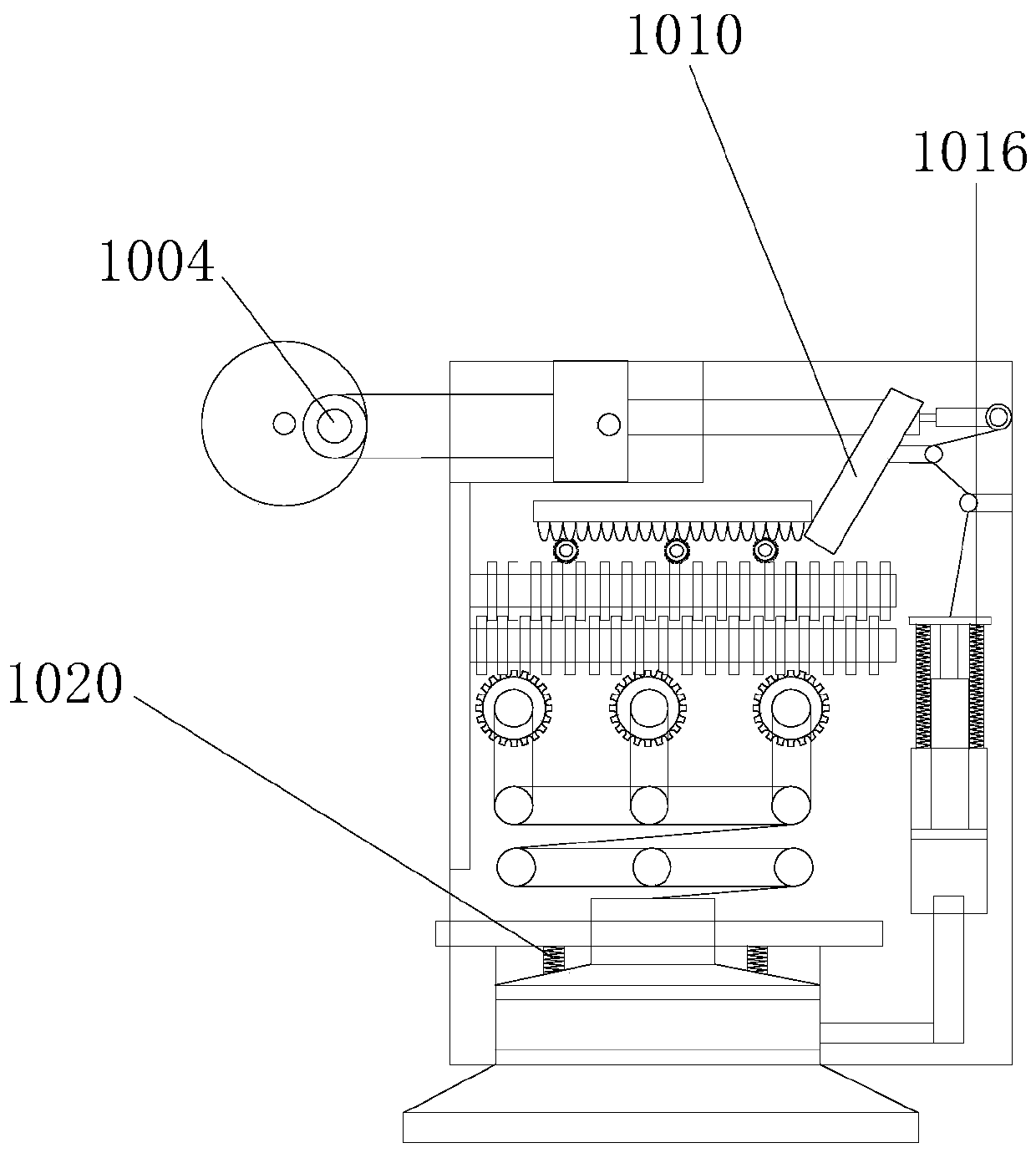
The invention discloses a remote monitoring system for medical equipment based on a communication network. Its structure includes a communication signal pole, a monitoring eye shell, a night vision lamp, an automatic focus knob, a camera, a rotating disk, a housing, a sound amplification hole, a fixed base, Suction cup fixing mechanism, the suction cup fixing mechanism is located at the bottom of the front end of the casing, the casing and the suction cup fixing mechanism adopt clearance fit, the disk fixing mechanism consists of a transmission shaft, a first gear, a screw rod, a rocker, a rocker plate, a push rod, and a push block, horizontal connecting rod, rack, vertical connecting rod, transmission sliding rod, transmission rope, second gear, pressing rod, piston rod, first telescopic spring, piston block, piston pipe, through pipe, second telescopic spring, Suction cup, the user does not need to ask a professional installer to install it, and the user can install it by himself, and it is easy to install, strong in fixing performance, and convenient to disassemble. The user only needs to operate a rocker, which saves installation time and also Does not affect the beauty of the wall after dismantling.
Description
technical field [0001] The invention is a communication network-based remote monitoring system for medical equipment, which belongs to the field of monitoring systems. Background technique [0002] A typical TV monitoring system is mainly composed of five parts: front-end monitoring equipment, transmission equipment, back-end storage, control and display equipment. The back-end equipment can be further divided into central control equipment and sub-control equipment. There are many ways to form the front and back-end equipment, and the connection between them (also called the transmission system) can be realized by cables, optical fibers, microwaves, etc. Horizontal and vertical movement. The cloud platform we are talking about is different from the cloud platform in photographic equipment. Generally speaking, the cloud platform of photographic equipment is just a tripod, and the orientation can only be adjusted by hand; while the cloud platform mentioned by the monitoring ...
Claims
Application Information
Patent Timeline
Application Date:The date an application was filed.
Publication Date:The date a patent or application was officially published.
First Publication Date:The earliest publication date of a patent with the same application number.
Issue Date:Publication date of the patent grant document.
PCT Entry Date:The Entry date of PCT National Phase.
Estimated Expiry Date:The statutory expiry date of a patent right according to the Patent Law, and it is the longest term of protection that the patent right can achieve without the termination of the patent right due to other reasons(Term extension factor has been taken into account ).
Invalid Date:Actual expiry date is based on effective date or publication date of legal transaction data of invalid patent.