
Multifunctional molecular sieve dehydrating tower

A technology of molecular sieve and dehydration tower, which is applied in the field of multifunctional molecular sieve dehydration tower, can solve the problems of easily damaged internal heating natural gas molecular sieve dehydration device and reduce the service life of internal heating natural gas molecular sieve dehydration device, etc.

Pending Publication Date: 2018-05-08
四川科比科油气工程有限公司
View PDF14 Cites 0 Cited by
  • Summary
  • Abstract
  • Description
  • Claims
  • Application Information

AI Technical Summary

Problems solved by technology

The center tube, support screen and shell of the existing internal heating type natural gas molecular sieve dehydration device are welded together. Due to the alternating change of molecular sieve adsorption and regeneration, the thermal expansion and contraction effect of the center tube will affect the support screen and / or shell. The body produces alternating stress, which is easy to damage the internal heating type natural gas molecular sieve dehydration device, thereby reducing the service life of the internal heating type natural gas molecular sieve dehydration device

Method used


Image

  • Multifunctional molecular sieve dehydrating tower
  • Multifunctional molecular sieve dehydrating tower
  • Multifunctional molecular sieve dehydrating tower

Examples


Embodiment 1

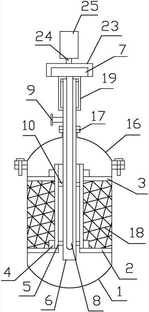
[0032] like Figure 1~3As shown, the multifunctional molecular sieve dehydration tower of the present invention includes a vertical cylindrical shell 1, and a first supporting mesh plate 2 is arranged in the shell 1 near the axial bottom end, and a first support screen 2 is arranged in the shell 1 near the axial top end. A second support net plate 3 is provided, and the center of the first support net plate 2 and the second support net plate 3 are provided with installation through holes, and the upper support net plate 2 and the second support net plate 3 There is a threaded connection sleeve 4 protruding from the center of the circle on the surface of the board; it also includes a mounting sleeve 5 and a central sleeve 6, and the axial top and bottom outer walls of the mounting sleeve 5 are provided with the threaded sleeve 5. The external thread of the connecting sleeve 4 is adapted, and the mounting sleeve 5 is installed on the first support net plate 2 and the second supp...

Embodiment 2

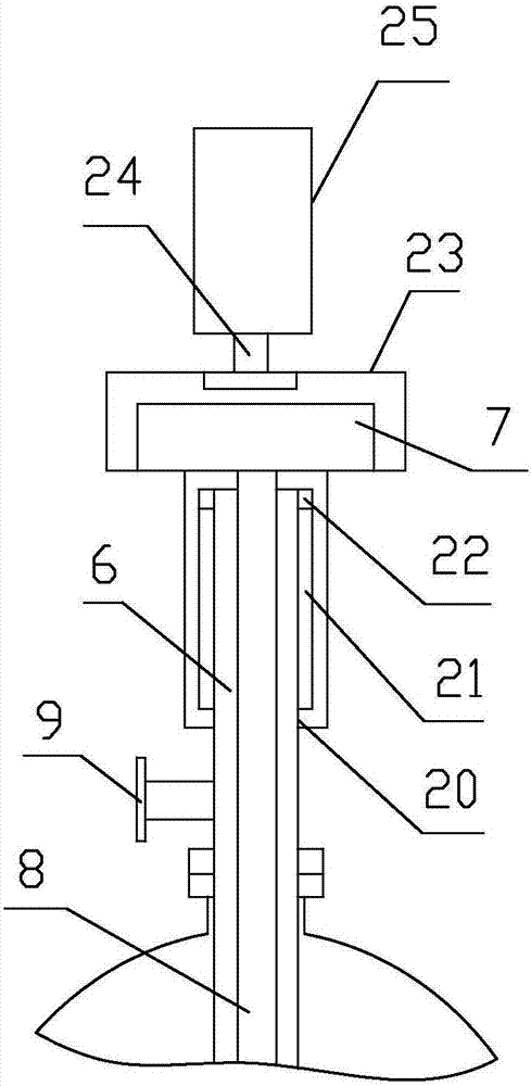
[0034] Further improvement on the basis of Example 1, the adjustment sleeve 19 is provided with a threaded through hole 20 and an adjustment hole 21 in sequence from the outside to the inside, the axis line of the adjustment sleeve 19 and the axis center of the threaded through hole 20 line and the axis line of the adjustment hole 21 all coincide; the inner diameter of the adjustment hole 21 is greater than the inner diameter of the threaded through hole 21, the threaded through hole 20 is adapted to the external thread of the central sleeve 6, and the axial top end of the central sleeve 6 A limiting plate 22 is arranged around the side wall along the axial direction, and the outer diameter of the limiting plate 22 is smaller than the inner diameter of the adjustment hole 21 and larger than the inner diameter of the threaded through hole 20 . The axial top end of the adjustment sleeve 19 is welded with an installation housing 23, which is used to install the electric heater 7 i...

Embodiment 3

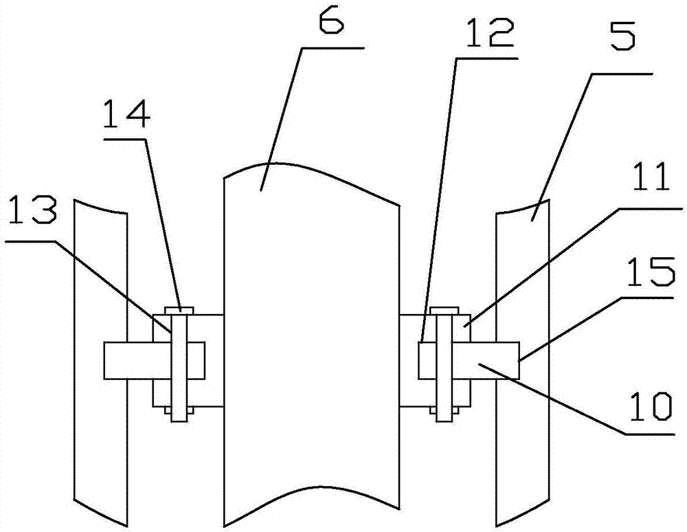
[0036] Further improvement on the basis of Embodiment 2, the side wall of the central sleeve 6 is provided with a mounting block 11 along the circumferential ring, the side wall of the mounting block 11 is provided with a limiting groove 12 along the circumferential ring, and the mounting block 9 is also provided with There is a threaded hole 13, the axial direction of the threaded hole 13 is perpendicular to the extension direction of the limiting groove 12, and the threaded hole 13 runs through the limiting groove 12; the rubber sealing ring 10 is sleeved on the mounting hole 11, and The radial end is embedded in the limiting groove 12 for sealing rubber ring installation, and the rubber sealing ring 10 is fixed on the mounting block 11 through the threaded hole 13 on the mounting block 11 and the rubber sealing ring 10 embedded in the limiting groove 12 through the bolt 14; The part of the rubber sealing ring 10 located outside the limiting groove 12 is pressed and fixed wit...


PUM


Abstract

The invention discloses a multifunctional molecular sieve dehydrating tower. A first support screen plate and a second support screen plate are arranged in a shell; mounting through holes are formed in the first support screen plate and the second support screen plate; threaded connection sleeves are arranged on the upper plate surfaces of the first support screen plate and the second support screen plate; mounting sleeves are in threaded connection with the threaded connection sleeves to be mounted on the first support screen plate and the second support screen plate; a center sleeve is inserted into the shell from the top of the shell and extends into the mounting sleeves and reaches a cavity between the lower plate surface of the first support screen plate and the inner bottom wall of the shell; the outer wall of the center sleeve is in seal connection with the inner walls of the mounting sleeves through a rubber seal ring; an adjusting sleeve is sleeved on the axial upper section of the center sleeve through threaded fit; an electric heating pipe of an electric heater at the top end of the adjusting sleeve passes through the top end of the adjusting sleeve and extends into thecenter sleeve in the shell. The multifunctional molecular sieve dehydrating tower disclosed by the invention has the advantage that the damage of the support screen plates and the shell caused by theheat-expansion and cold-contraction effect of the electric heating pipe can be effectively avoided.

Description

technical field [0001] The invention relates to the technical field of oil and gas treatment, in particular to a multifunctional molecular sieve dehydration tower. Background technique [0002] Since the existence of liquid water in natural gas will seriously affect the safety of automobiles and filling stations, it is necessary to dehydrate natural gas so that the dehydrated natural gas meets safety standards. The center tube, support screen and shell of the existing internal heating type natural gas molecular sieve dehydration device are welded together. Due to the alternating change of molecular sieve adsorption and regeneration, the thermal expansion and contraction effect of the center tube will affect the support screen and / or shell. The body produces alternating stress, which is easy to damage the internal heating type natural gas molecular sieve dehydration device, thereby reducing the service life of the internal heating type natural gas molecular sieve dehydration ...

Claims


Application Information

Patent Timeline
Patent Type & Authority Applications(China)
IPC IPC(8): B01D53/26B01D53/04C10L3/10
CPCB01D53/04B01D53/261C10L3/106B01D2253/106
Inventor 陈斯刘敏朱江
Owner 四川科比科油气工程有限公司
Learn More