Ultrahigh-speed turbine applicable to high-temperature high-back pressure dry gas seal structure

A dry gas sealing, high back pressure technology, used in mechanical equipment, engine components, machines/engines, etc., can solve the problems of low wear resistance of dynamic seals, single non-adjustable output power, unstable elastic value changes, etc. The effect of improving wear resistance and reliability, improving bearing working environment and improving working reliability

Active Publication Date: 2018-05-08
BEIJING RES INST OF PRECISE MECHATRONICS CONTROLS
View PDF6 Cites 2 Cited by
  • Summary
  • Abstract
  • Description
  • Claims
  • Application Information

AI Technical Summary

Problems solved by technology

[0002] Under the condition of specific air source pressure, the existing small turbines basically have a relatively single output power and cannot be adjusted; and the dynamic seal in the structural design is mainly a contact mechanical dynamic seal, which is difficult for turbines with such a sealing structure to be suitable for high temperature In the working condition of high back pressure working fluid, or under the action of high temperature and high pressure working fluid, the wear resistance of the dynamic seal is low, which may easily lead to the failure of the dynamic seal; at the same time, during the high temperature working medium and long-term working process of the turbine, the bearing generated The heat is not easy to dissipate, which leads to the decrease of the working stability and reliability of the shaft system; and in the shaft system structure, most of the bearings adopt positioning preload or elastic wave ring type constant pressure preload, and the elastic wave ring has strong nonlinearity, and the change of elastic force value is relatively large. Large instability; based on the existing background technology, an ultra-high-speed turbine suitable for high-temperature and high-backpressure dry gas seal structure was designed and developed

Method used


Image

  • Ultrahigh-speed turbine applicable to high-temperature high-back pressure dry gas seal structure
  • Ultrahigh-speed turbine applicable to high-temperature high-back pressure dry gas seal structure
  • Ultrahigh-speed turbine applicable to high-temperature high-back pressure dry gas seal structure

Examples


Embodiment Construction

[0044] An ultra-high-speed turbine suitable for a high-temperature, high-backpressure dry gas sealing structure provided by the present invention will be further described in detail below with reference to the accompanying drawings and specific embodiments.

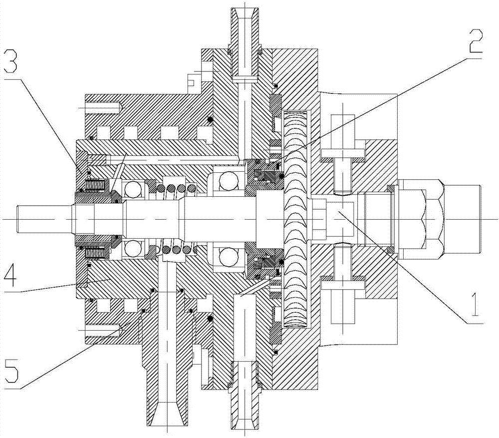
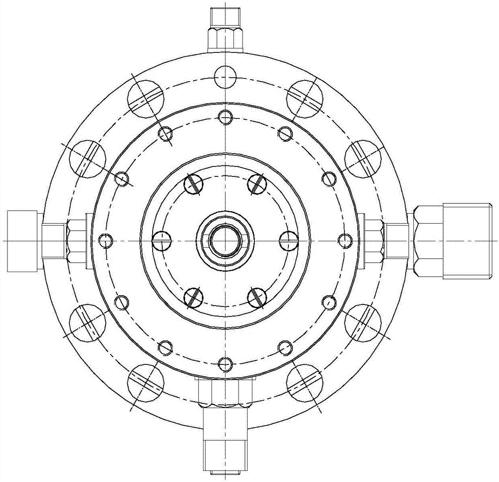
[0045] like figure 1 and figure 2 As shown, the present invention provides an ultra-high-speed turbine suitable for high temperature and high back pressure dry gas seal structure, including turbine shaft assembly 1, dry gas seal assembly 2, mechanical dynamic seal assembly 3, housing assembly 4, cooling water The sleeve assembly 5; the turbine shafting assembly 1 passes through and is installed inside the casing assembly 4, the dry gas seal assembly 2 is located inside the casing assembly 4 and connected with the turbine shafting assembly 1, and the cooling water jacket assembly 5 is positioned to install the casing assembly 1 outside, the mechanical dynamic seal assembly 3 is installed inside the housing assembly 4 and...


PUM


Abstract

The invention belongs to the technical field of turbines, and particularly relates to an ultrahigh-speed turbine applicable to a high-temperature high-back pressure dry gas seal structure. The ultrahigh-speed turbine comprises a turbine shaft assembly 1, a dry gas seal assembly 2, a mechanical dynamic seal assembly 3, a shell assembly 4 and a cooling water jacket assembly 5, wherein the turbine shaft assembly 1 penetrates through the shell assembly 4 and is mounted in the shell assembly 4; the dry gas seal assembly 2 is positioned in the shell assembly 4 and is connected with the turbine shaftassembly 1; the cooling water jacket assembly 5 is mounted at the outer part of the shell assembly 4; and the mechanical dynamic seal assembly 3 is mounted in the shell assembly 4 and is connected with the turbine shaft assembly 1. According to the ultrahigh-speed turbine, thermal energy of a liquid can be converted into ultrahigh-speed mechanical shaft power under the action of a special workingmedium.

Description

technical field [0001] The invention belongs to the technical field of turbines, and in particular relates to an ultra-high-speed turbine suitable for a high-temperature, high-backpressure dry gas sealing structure. Background technique [0002] Under the condition of specific air source pressure, the existing small turbines basically have a relatively single output power and cannot be adjusted; and the dynamic seal in the structural design is mainly a contact mechanical dynamic seal, which is difficult for turbines with such a sealing structure to be suitable for high temperature In the working condition of high back pressure working medium, or under the action of high temperature and high pressure working medium, the wear resistance of the dynamic seal is low, which may easily lead to the failure of the dynamic seal; at the same time, during the high temperature working medium and long-term working process of the turbine, the The heat is not easy to dissipate, which leads ...

Claims


Application Information

Patent Timeline
Patent Type & Authority Applications(China)
IPC IPC(8): F01D5/02F01D5/06F01D25/24F01D9/02F01D11/00F01D11/04F01D25/12F01D25/16
CPCF01D5/02F01D5/06F01D9/02F01D11/003F01D11/04F01D25/12F01D25/125F01D25/16F01D25/24
Inventor 郝小龙胡丽国李振将郭军刚王志峰
Owner BEIJING RES INST OF PRECISE MECHATRONICS CONTROLS
Why Eureka
Try Eureka