
Near-field antenna emission unit level measurement system

A technology of transmitting unit and near-field antenna, which is applied in the direction of antenna radiation pattern, etc., can solve the problems of not providing real-time position information output of the sampling rack, the test unit cannot be matched, and the effect is limited, so as to improve the test progress and near-field test Efficiency, saving measurement cost and labor cost, and avoiding large measurement errors

Inactive Publication Date: 2018-05-08
BEIJING INST OF RADIO MEASUREMENT
View PDF4 Cites 3 Cited by
  • Summary
  • Abstract
  • Description
  • Claims
  • Application Information

AI Technical Summary

Problems solved by technology

[0004] However, in the existing near-field test, because the system does not provide real-time position information output of the sampling rack, it cannot effectively inform the wave controller of the solid-state array antenna of the effective position of the current measurement unit, resulting in the test unit not being able to communicate with the wave controller. The unit is matched, so it is impossible to realize the function of "single opening and single collection"
As a result, the test time is longer, and the normal test time can reach more than 13 hours, and the test is affected by the ambient temperature, which leads to large errors, so additional calibration work is required, which is time-consuming and laborious, and the effect of calibration to reduce errors is limited, eventually resulting in even Through repeated calibration, the error is still large

Method used


Image

  • Near-field antenna emission unit level measurement system
  • Near-field antenna emission unit level measurement system
  • Near-field antenna emission unit level measurement system

Examples


Embodiment approach

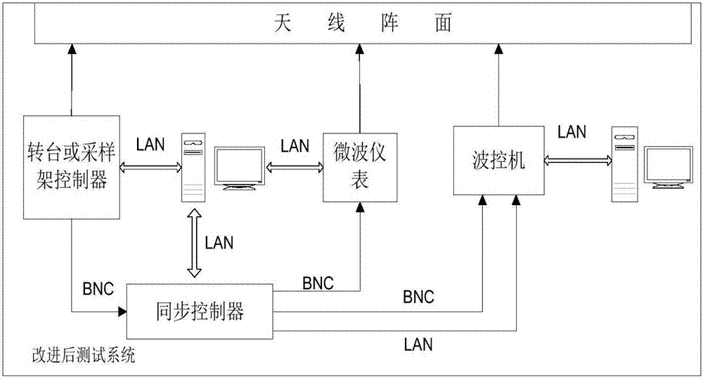
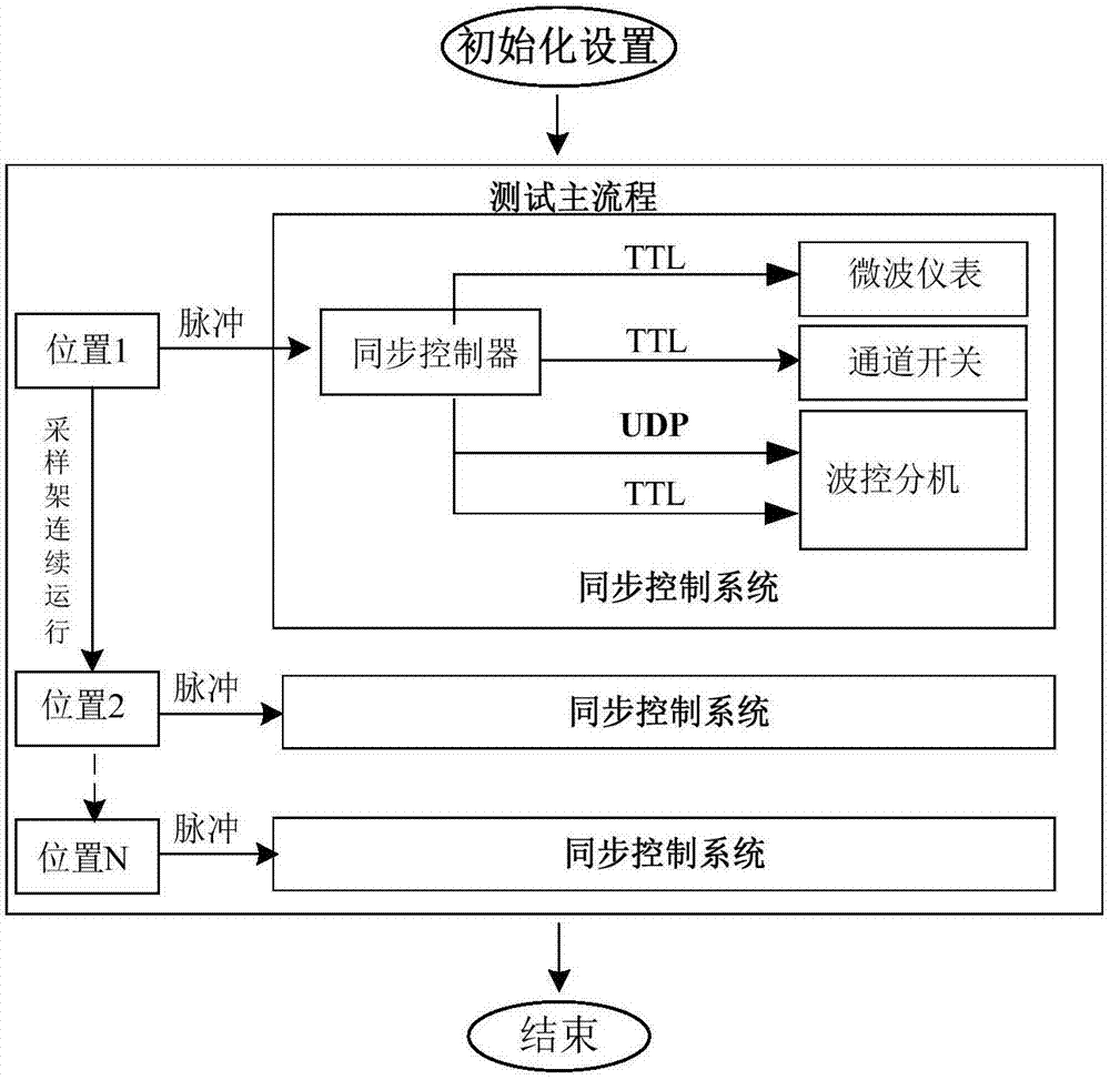
[0027] The present invention provides a specific implementation mode, a near-field antenna transmitting unit-level measurement system, including: a main controller, used to send initialization commands; a sampling rack controller, controlling the operation of the sampling rack according to the initialization commands; a wave control machine , for data collection; the measurement system also includes a synchronous controller, which is used to realize the synchronization of the sampling frame controller and the wave control machine.

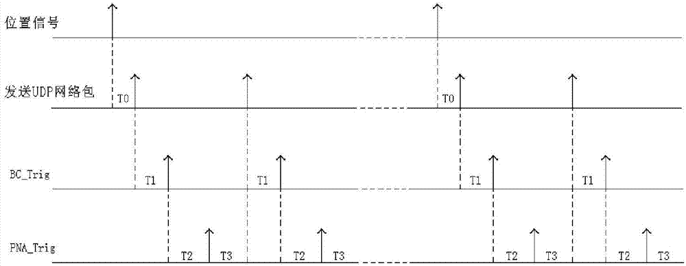
[0028] A near-field antenna transmitting unit-level measurement system in this embodiment, in the test system of the prior art, a synchronous controller is added to make the test system communicate with the wave controller, so as to achieve the purpose of high-speed measurement and save measurement time , avoiding the problem of large measurement error due to excessive ambient temperature difference caused by too long time, thereby improving the tes...


PUM


Abstract

The invention discloses a near-field antenna emission unit level measurement system which includes a master control machine used for sending an initialization command, a sampling frame controller usedfor controlling the operation of a sampling frame according to the initialization command, and a wave control machine used for data acquisition. The measurement system further includes a synchronization controller used for synchronizing the sampling frame controller and the wave control machine. By using the system of the invention, the problem that the measurement error is large due to large environmental temperature difference caused by too long time is avoided, and the test progress and the near-field test efficiency are improved. Moreover, there is no need for a calibration link on the basis of the prior art, and the measurement cost and the labor cost are greatly saved.

Description

technical field [0001] The invention relates to the field of near-field antenna measurement. More specifically, it relates to a near-field antenna transmitting unit-level measurement system. Background technique [0002] With the rapid development of modern radar solid-state phased array antenna technology, phased array antennas have become dominant, and their transmission power and number of units are also increasing. At present, the total transmitting power of the solid-state phased array antenna can reach the order of hundreds of kilowatts, and the number of units can reach as many as 20,000. Solid-state phased array antennas can no longer transmit in the near-field test like its receiving state test. All units can be opened for testing. If all units are opened, the test equipment, anechoic absorbing materials, and test personnel will all be exposed to high power. Electromagnetic radiation, which is likely to cause damage to instruments and equipment, smoldering of the ...

Claims


Application Information

Patent Timeline
Patent Type & Authority Applications(China)
IPC IPC(8): G01R29/10
CPCG01R29/10
Inventor 胡耀宗魏凯
Owner BEIJING INST OF RADIO MEASUREMENT
Learn More