Antenna elastic piece and electronic equipment

A technology of antenna shrapnel and contact elements, which is applied in the direction of circuits, electrical components, conductive connections, etc., can solve the problems that antenna shrapnel cannot meet the design requirements and the available space is small, and meet the needs of electrical contact and miniaturization Effect

Inactive Publication Date: 2018-05-08
河源市美晨联合智能硬件电子研究院 +2
View PDF6 Cites 0 Cited by
  • Summary
  • Abstract
  • Description
  • Claims
  • Application Information

AI Technical Summary

Problems solved by technology

This undoubtedly causes the antenna space of electronic equipment to be continuously compressed, and the available space is getting smaller and smaller, which makes the existing antenna shrapnel more and more unable to meet the design requirements.

Method used


Image

  • Antenna elastic piece and electronic equipment
  • Antenna elastic piece and electronic equipment
  • Antenna elastic piece and electronic equipment

Examples


Embodiment Construction

[0020] The following will clearly and completely describe the technical solutions of each exemplary embodiment provided by the present invention with reference to the accompanying drawings in the following embodiments. In the case of no conflict, the following embodiments and the technical features in the embodiments can be combined with each other. Moreover, the directional terms used throughout the present invention, such as "upper" and "lower", are for better describing various embodiments, and are not used to limit the protection scope of the present invention.

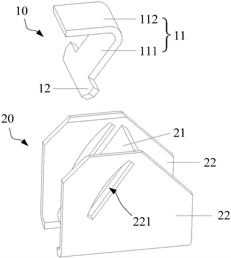
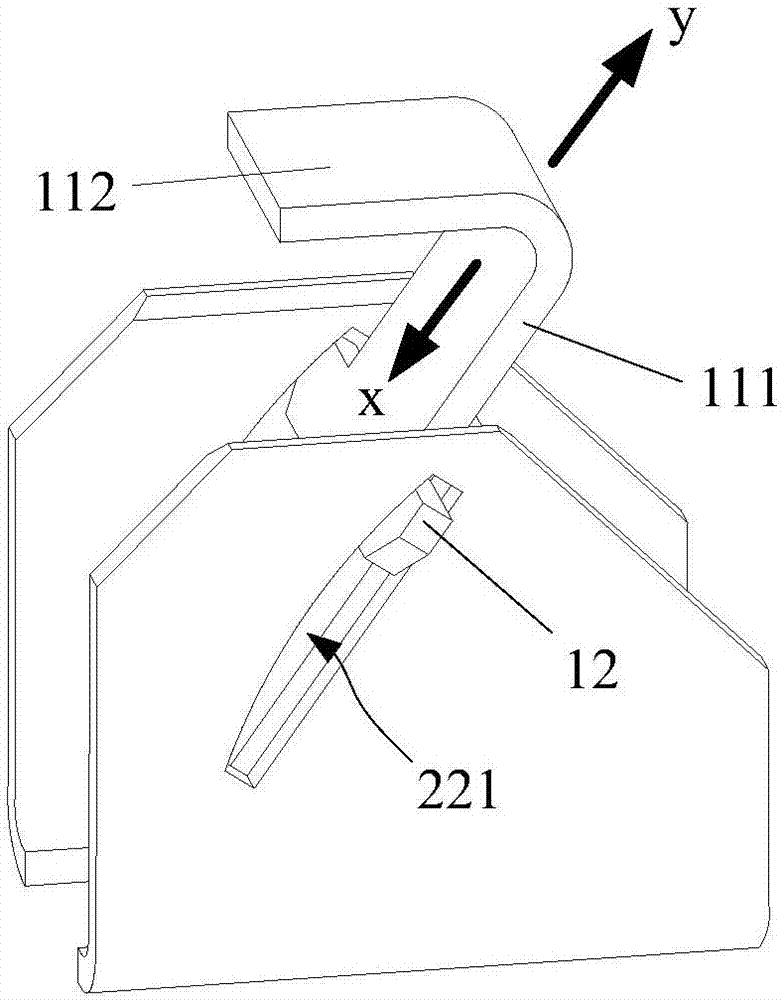
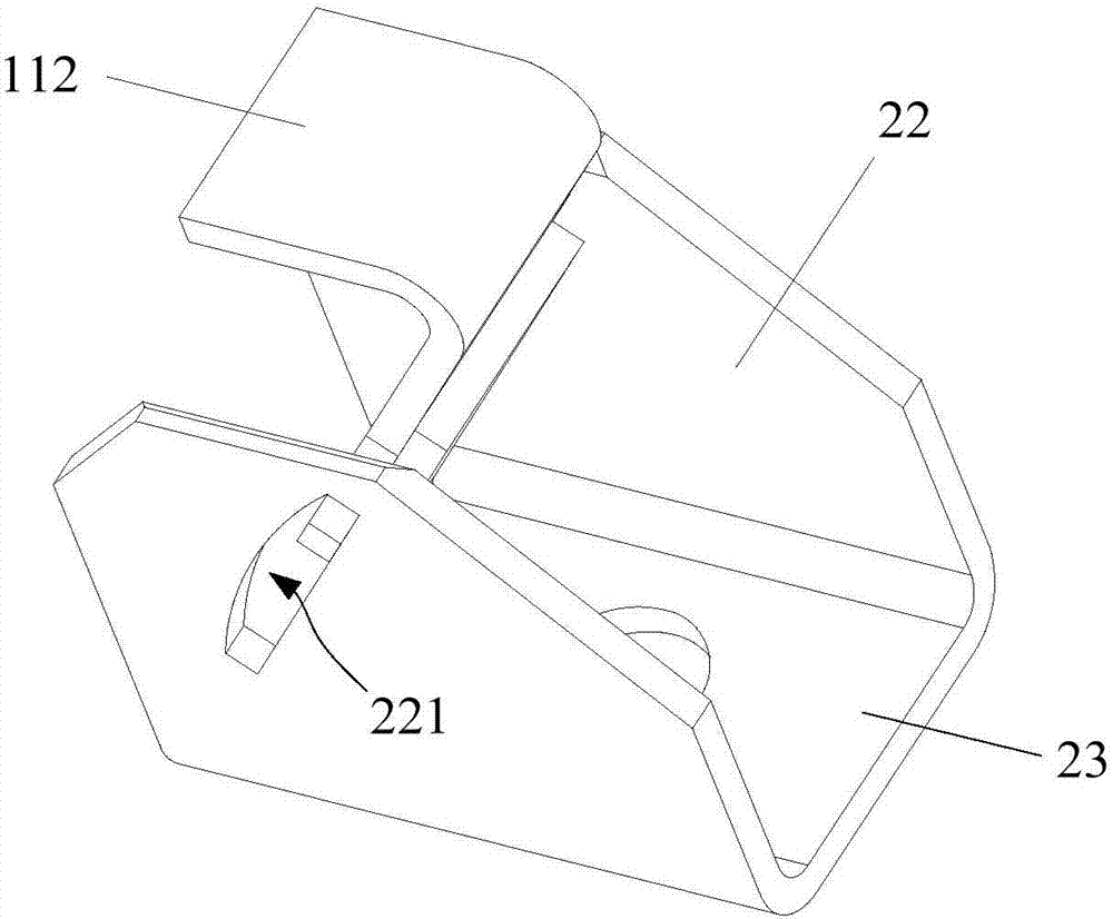
[0021] figure 1 It is an exploded schematic view of the structure of the antenna shrapnel according to the first embodiment of the present invention. see figure 1 , the antenna shrapnel includes a detachably connected contact element 10 and a welding element 20, the contact element 10 is used for electrical contact with the antenna provided on the housing of the electronic device, and the welding element 20 is u...


PUM


Abstract

The invention discloses an antenna elastic piece and electronic equipment. The antenna elastic piece comprises a contact element and a welding element, wherein the welding element is provided with a laminating part; the contact element is detachably connected with the welding element, and when the two are connected, the contact element is contacted with the surface of the laminating part; the contact element can perform to-and-fro movement along a first direction and an opposite second direction on the laminating part, the height of the antenna elastic piece is the minimum when the contact element moves along the first direction to an extreme position, the height of the antenna elastic piece is the maximum when the contact element moves along the second direction to an extreme position, and during the to-and-fro movement process, the contact element is always contacted with the surface of the laminating part. Thus, the miniaturization demands of the antenna elastic piece can be met, and light weight, thinness and a high screen ratio of the electronic equipment can be realized.

Description

technical field [0001] The invention relates to the technical field of antennas, in particular to an antenna shrapnel and electronic equipment. Background technique [0002] The antenna is generally arranged on the back cover or the casing of the electronic device, and usually needs to transmit the antenna signal to the main board of the electronic device through the shrapnel assembly. The current antenna shrapnel is generally welded on one side of the PCB (Printed Circuit Board, printed circuit board) of the main board and docked with the antenna on the housing. Realize the electrical contact between the motherboard and the antenna, so as to realize the transmission of signals. [0003] As the current society has higher and higher requirements for fashion, portability, and functionality of electronic equipment, reducing the thickness of electronic equipment to achieve thinner and lighter mobile phones and high screen-to-body ratio has become a mainstream trend. Undoubtedl...

Claims


Application Information

Patent Timeline
Patent Type & Authority Applications(China)
IPC IPC(8): H01R12/57H01R4/48
CPCH01R12/57H01R4/4809
Inventor 倪漫利刘雷韩成
Owner 河源市美晨联合智能硬件电子研究院
Why Eureka
Try Eureka