
Large-visual field high-performance ultra-small microscope objective lens

A microscopic objective lens, a high-performance technology, applied in the field of optical imaging, can solve the problems that the efficiency of pathological diagnosis has not been improved, the development and application of digital pathology technology is limited, and the imaging speed of digital pathology images is slow, so as to meet the needs of efficient and accurate application. Objective lens The effect of volume reduction and production difficulty reduction

Pending Publication Date: 2019-09-06
DAKEWE SHENZHEN MEDICAL EQUIP CO LTD
View PDF0 Cites 2 Cited by
  • Summary
  • Abstract
  • Description
  • Claims
  • Application Information

AI Technical Summary

Problems solved by technology

However, at present, traditional microscope objectives are still used in digital pathology equipment. Due to the limitations of traditional microscope objectives, many problems have been transferred from pathological diagnosis to the pathological slide scanning process before pathological diagnosis, resulting in the speed of digital pathology image imaging. It usually takes tens of minutes to complete a digital scan of a slice. Therefore, although digital pathology technology can reduce the burden and labor intensity of pathologists to a certain extent, and improve the accuracy of pathological diagnosis to a certain extent, the The efficiency is still not improved, even lower than traditional pathological diagnosis, which seriously limits the development of digital pathology technology and its clinical application

Method used


Image

  • Large-visual field high-performance ultra-small microscope objective lens
  • Large-visual field high-performance ultra-small microscope objective lens
  • Large-visual field high-performance ultra-small microscope objective lens

Examples


Embodiment Construction

[0035] The following will clearly and completely describe the technical solutions in the embodiments of the present invention with reference to the accompanying drawings in the embodiments of the present invention. Obviously, the described embodiments are only part of the embodiments of the present invention, not all of them. Based on the embodiments of the present invention, all other embodiments obtained by persons of ordinary skill in the art without creative efforts fall within the protection scope of the present invention.

[0036] It should be noted that if there is a directional indication (such as up, down, left, right, front, back...) in the embodiment of the present invention, the directional indication is only used to explain the position in a certain posture (as shown in the accompanying drawing). If the specific posture changes, the directional indication will also change accordingly.

[0037] The ultra-small microscopic objective optical system with large field o...


PUM


Abstract

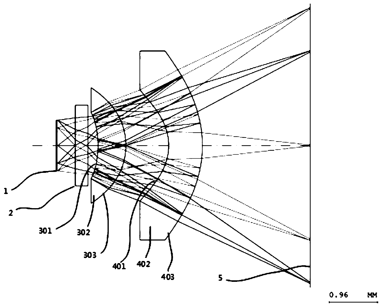
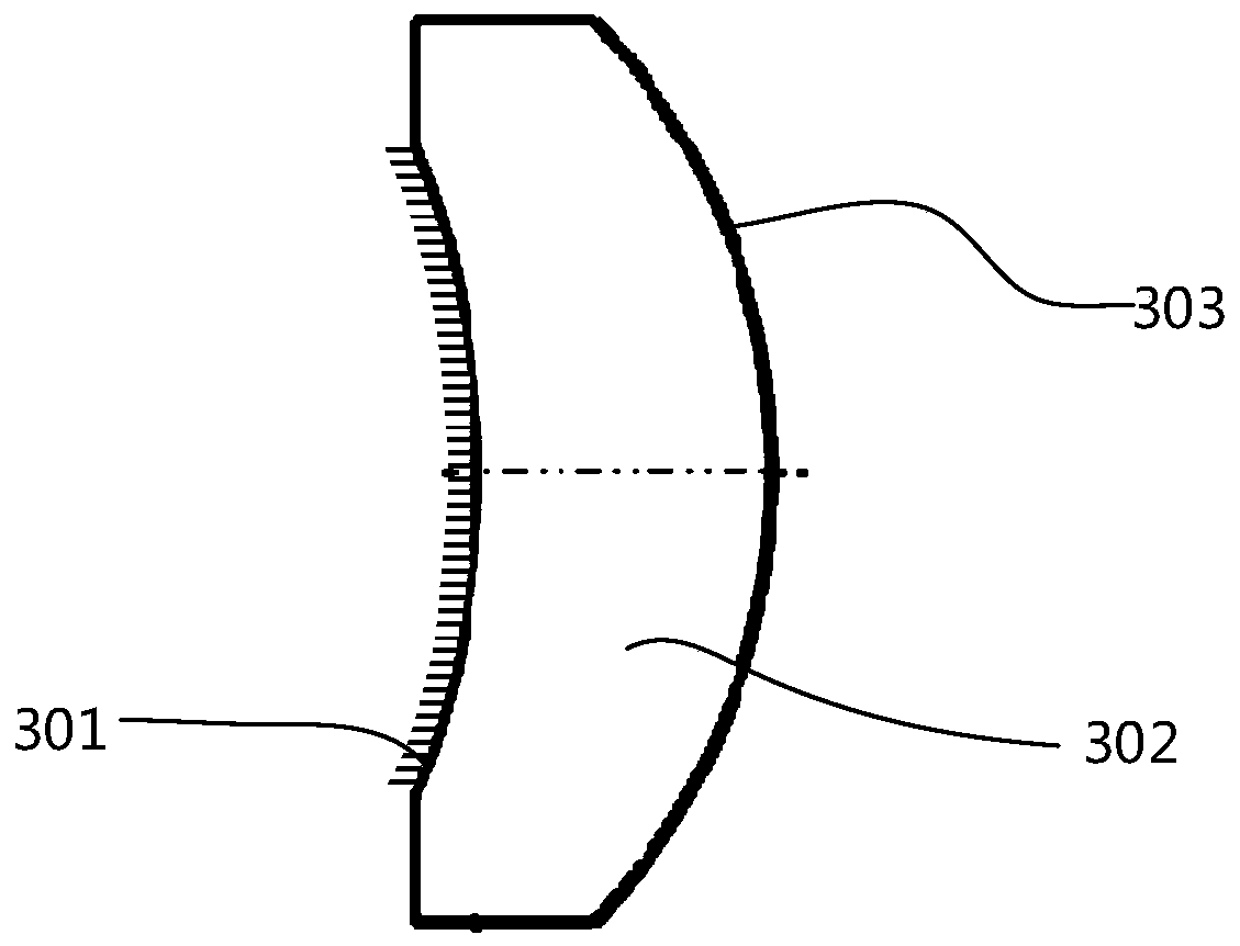
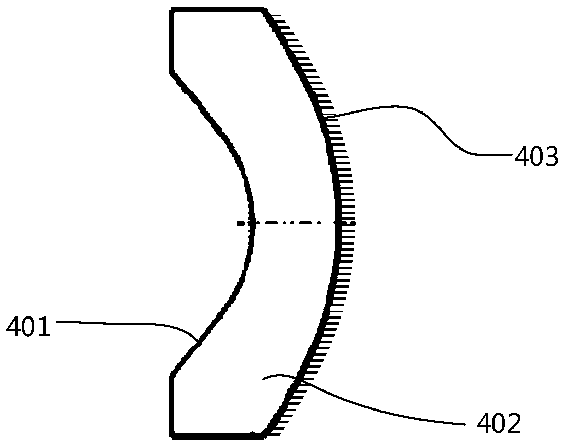
The invention discloses a large-visual field high-performance ultra-small microscope objective lens. The large-visual field high-performance ultra-small microscope objective lens is a catadioptric optical system, and comprises a first lens and a second lens sequentially along an optical axis direction, wherein both the first lens and the second lens are meniscus lenses, the surface facing an object surface is a concave surface, the surface facing an image surface is a convex surface, the object surface-facing surface of the first lens is a front surface, the image surface-facing surface of thesecond lens is a rear surface, and both surfaces are coated with half transparent and half reflecting optical medium spectrophotometric films; an aperture diaphragm is located on the rear surface facing the image surface of the first lens; the front end, located on the front surface of the first lens, of the object surface has a far limiting position; and the rear end, located on the rear surfaceof the second lens, of the image surface has a far limiting position. By adopting the catadioptric structure, the maximum diffraction path of light in the system is realized concisely, and the diffraction limit is reached. One embodiment of the invention realizes that the diameter of the visual field range is 1 mm, the numerical aperture is 0.6, the total system length is 4.23 mm, the magnification is 5.14, and the imaging resolution is 0.24 microns / pixel.

Description

technical field [0001] The invention relates to the field of optical imaging, in particular to an ultra-small microscopic objective lens with a large field of view and high performance. Background technique [0002] The microscope objective lens is one of the indispensable and important optical components in the optical microscope system. It is used at the front end of the microscope equipment and is the first lens in the microscope optical system to receive the light from the object to be observed. Generally speaking, a microscope objective lens is composed of an entrance pupil lens, an aperture stop, an intermediate lens or a combination of intermediate lenses, and an exit pupil lens. The light from the observed object first passes through the entrance pupil lens and shines into the lens barrel, then is magnified under the action of the aperture stop and the intermediate lens, and finally shines out of the lens barrel through the exit pupil lens to achieve a clear image i...

Claims


Application Information

Patent Timeline
IPC IPC(8): G02B21/04G02B17/08
CPCG02B21/04G02B17/0804
Inventor 于綦悦何俊峰吴庆军唐玉豪邓建刘亚鸿
Owner DAKEWE SHENZHEN MEDICAL EQUIP CO LTD
Learn More