
OBU production test equipment

A technology for production testing and equipment, applied in the field of testing, can solve problems such as increasing production costs, and achieve the effects of convenient testing, centralized testing stations, and reduced manual judgment links

Pending Publication Date: 2018-05-08
重庆通慧网联科技有限公司
View PDF4 Cites 5 Cited by
  • Summary
  • Abstract
  • Description
  • Claims
  • Application Information

AI Technical Summary

Problems solved by technology

OBU production needs to carry out multiple index detection, especially the transmission power and receiving sensitivity inspection, which often requires expensive radio frequency equipment; current detection in various states requires a current tester, plus manual judgment of sound, display and other tests, These all greatly increase the production cost, so we propose an OBU production test equipment

Method used


Image

  • OBU production test equipment
  • OBU production test equipment

Examples


Embodiment Construction

[0014] The following will clearly and completely describe the technical solutions in the embodiments of the present invention with reference to the accompanying drawings in the embodiments of the present invention. Obviously, the described embodiments are only some, not all, embodiments of the present invention. Based on the embodiments of the present invention, all other embodiments obtained by persons of ordinary skill in the art without making creative efforts belong to the protection scope of the present invention.

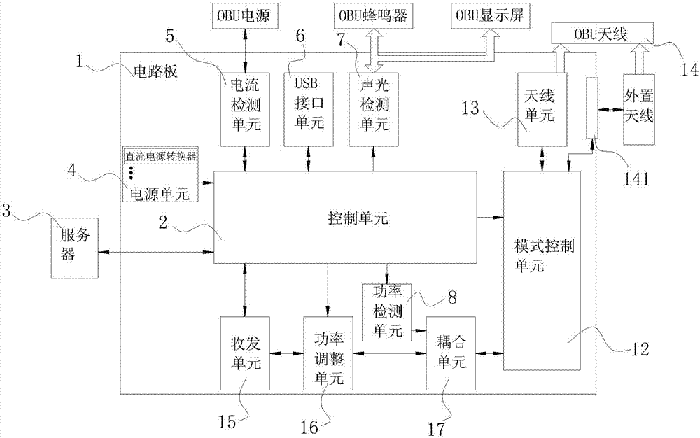
[0015] see Figure 1-2 , the present invention provides a technical solution: a kind of OBU production and testing equipment, including a circuit board 1, the middle part of the circuit board 1 is welded with a control unit 2, the control unit 2 is the core control center of the equipment, and controls the functions of each unit For execution, a power supply unit 4 is welded on the upper left side of the circuit board 1, and a set of DC power converters are bu...


PUM


Abstract

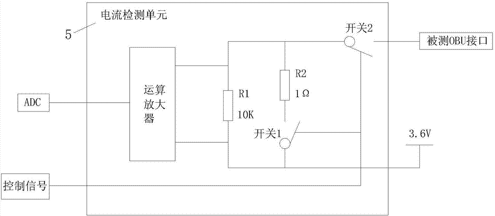
The invention discloses an OBU production test device including a circuit board. A control unit is welded in the middle of the circuit board. A power supply unit is welded on the upper left part of the circuit board. The lower left part of the control unit is connected to a server through a communication interface. A current detection unit is welded on the upper left side of the circuit board. Thecurrent detection unit comprises an operational amplifier, a resistor 1, a resistor 2, a switch 1 and a switch 2. A USB interface unit is welded to the right side of the circuit board. An acousto-optic detection unit is welded on the right side of the USB interface unit. The right side of the acousto-optic detection unit is provided with a power detection unit. The current detection unit is connected to an OBU power supply in series through a conductive wire. According to the OBU production test device, through integrating overall structures of multiple test methods, the production efficiencyis greatly improved.

Description

technical field [0001] The invention relates to the technical field of detection, in particular to an OBU production and testing equipment. Background technique [0002] Radio frequency identification non-stop charging system is currently the most advanced road and bridge toll collection method. Through the dedicated short-range communication between the on-board unit installed on the vehicle windshield and the road test unit on the ETC lane of the toll station, the computer networking technology is used to carry out background settlement processing with the bank, so that the vehicle does not need to stop when passing through the road and bridge toll station For the purpose of paying fees, the circulation of OBU is huge and the market competition is fierce. Lower OBU cost is very critical to improve product competitiveness. Therefore, improving production efficiency and reducing production costs are the concerns of various equipment manufacturers. OBU production needs to ...

Claims


Application Information

Patent Timeline
IPC IPC(8): H04B17/15H04B17/29G01R19/25H04B5/00
CPCH04B17/15H04B17/29G01R19/25H04B5/77H04B5/73
Inventor 张浩李泳良周世华王永刚
Owner 重庆通慧网联科技有限公司
Learn More