Pressurizing toggle joint punching machine

A technology of toggle and punch presses, applied in the field of pressurized toggle presses, which can solve problems such as slow running speed of equipment, short ejection strokes, and locked punches, so as to improve production efficiency, increase ejection strokes, and increase driving force Effect

Pending Publication Date: 2018-05-11
JIAXING DA DAO FORGING TECH CONSULTING LTD
View PDF1 Cites 3 Cited by
  • Summary
  • Abstract
  • Description
  • Claims
  • Application Information

AI Technical Summary

Problems solved by technology

[0004] Both the above-mentioned punch presses and the existing toggle punch presses are driven by a flywheel driven by a motor, which drives the crankshaft to rotate to drive the connecting rod to pull the toggle angle, and drives the slider to move up and down to complete the forged product. The disadvantages of the above-mentioned driving method are as follows: 1. Crankshaft drive The force at each angle is different, the maximum at 180 degrees and the minimum at 0 degrees (very small); 2. The stroke length is fixed and cannot be adjusted (driven by the crankshaft turning one circle); 3. When the actual load is greater than that of the punching machine When the load is rated, it will cause the punch press to lock up and damage the punch press; 4. The existing large-tonnage hydraulic press must be equipped with a large oil cylinder, a large oil tank, a large oil pump, and a large flow control valve, which is expensive, and the equipment runs slowly and consumes a lot of energy; 5. The structure adopted by the existing mechanical press lower material ejection structure, either the ejection stroke is very short, or the ejection force is very small, and it is impossible to achieve a large ejection force and a large ejection stroke at the same time

Method used


Image

  • Pressurizing toggle joint punching machine
  • Pressurizing toggle joint punching machine
  • Pressurizing toggle joint punching machine

Examples


Embodiment 1

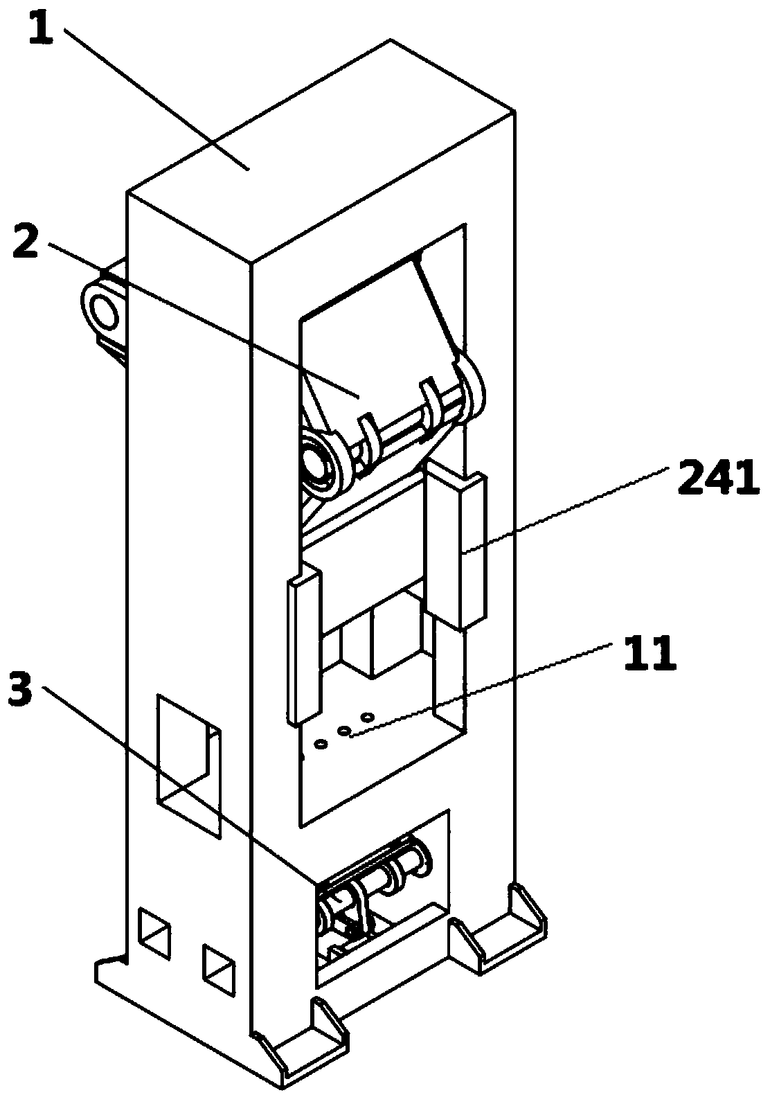
[0037] Such as figure 1 As shown, a pressurized toggle press includes a frame 1, a slider assembly 2 and an ejector assembly 3, and the slider assembly 2 is arranged on the frame 1 opposite to the ejector assembly 2, and the The frame 1 is provided with a through hole 11 through which the jacking assembly 2 protrudes.

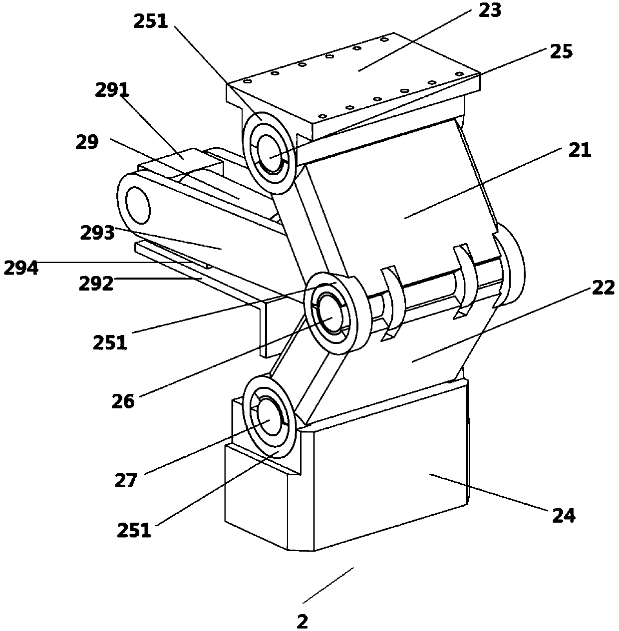
[0038] The slider assembly 2 includes an upper toggle 21, a lower toggle 22, a toggle holder 23 and a slider 24, the upper toggle 21 is fixed with the frame 1 through an upper shaft 25, and the lower toggle 22 is fixed with the slider 24 through the lower shaft 27, a central shaft 26 is arranged between the upper toggle 21 and the lower toggle 22, and the central shaft 26 is connected with a driving device, and the driving device drives The upper toggle 21 and the lower toggle 22 perform telescopic movement;

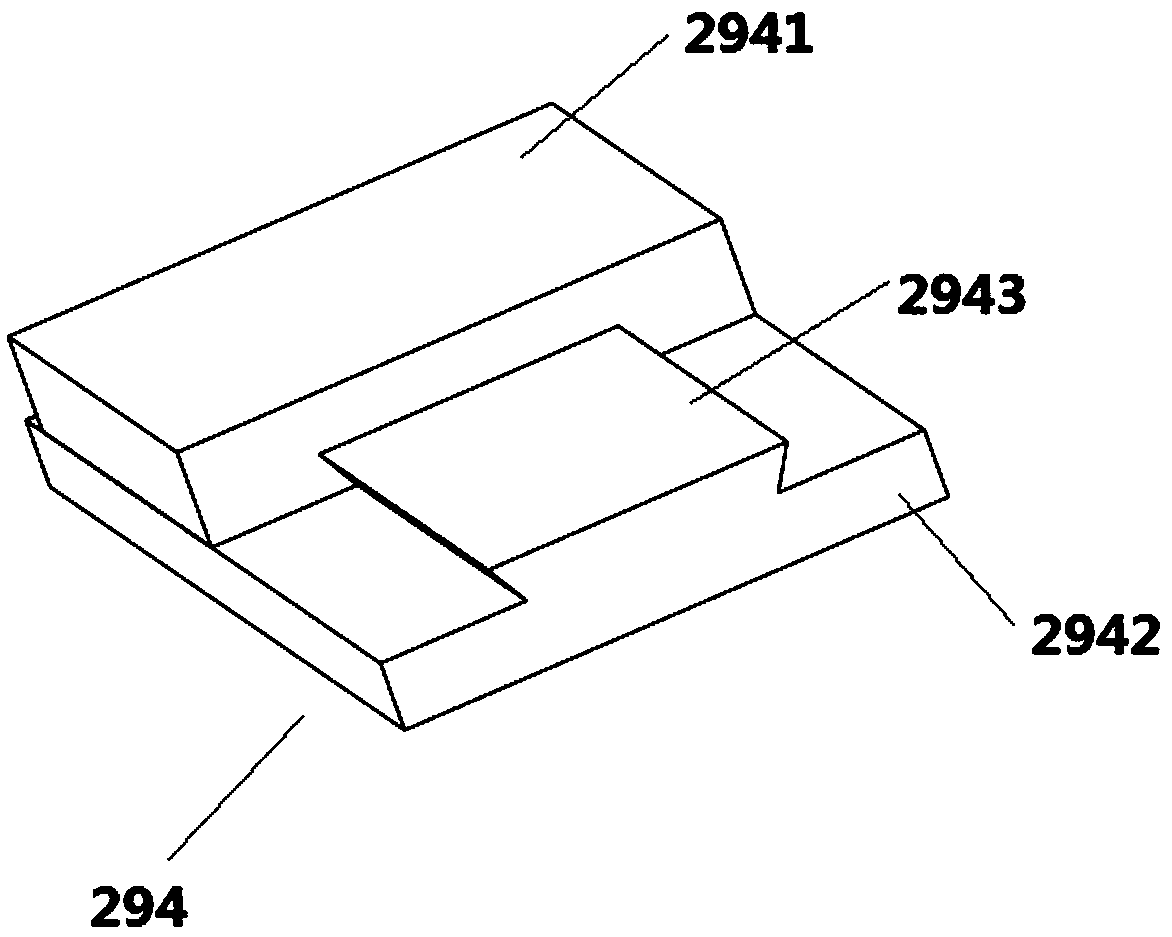
[0039] Described driving device one comprises slide block oil cylinder 29, slide block oil cylinder base 291, carriage 292 and slide rail device 294, a...

Embodiment 2

[0059] Such as Figure 12 and 13 As shown, the driving device one is a servo motor 7 in this embodiment, and the driving device one also includes a small gear 71, a large gear 72, a screw 73 and a nut 74, and the driving device also includes a servo motor base, a bracket 292 and Slide rail device 294, the servo motor 7 is arranged on the bracket 292, the bracket 292 is fixedly connected with the frame 1, the servo motor is matched with an effective gear 71, and the pinion 71 is connected to the The large gear 72 meshes, and then the rotation of the large gear 72 can be driven when the servo motor 7 drives the small gear 71 to rotate. The big gear 72 is connected with a screw 74 , the screw 74 is connected with the central shaft 26 , and the slide rail device 294 is arranged between the bracket 292 and the slider oil cylinder base 291 .

[0060] When the driving device is the servo motor 7, the motion mode is: the servo motor 7 drives the pinion 71, the pinion 71 drives the b...


PUM


Abstract

The invention discloses a pressurizing toggle joint punching machine which comprises a rack, a sliding block assembly and an ejection assembly. The sliding block assembly and the ejection assembly areoppositely arranged on the rack, the rack is provided with a through hole allowing the ejection assembly to extend out, the ejection assembly comprises an ejection rod device and a connecting rod device, the ejection rod device is arranged at the upper end of the connecting rod device, and the ejection rod device ascends and descends along with ascending and descending of the connecting rod device. The pressurizing toggle joint punching machine has the beneficial effects that the manner that an oil cylinder drives a toggle joint is adopted, driving force of the oil cylinder is increased, 5-7times of driving force can be increased, cost is saved, and the production efficiency is improved; and a unique lower ejection structure is adopted, according to the characteristics that ejection force needed in the early period during ejection is large and the ejection force needed after a product is loosened is small are used, a single-edge cam is used for ejection in the early period during ejection, the lever principle is used, the ejection force is increased, two-edge cams are used in the later period for ejection at the same time, and the ejection stroke is increased.

Description

technical field [0001] The invention relates to the field of mechanical equipment, in particular to a pressurized toggle press. Background technique [0002] Punching machines are widely used in stamping and forming in various fields. [0003] Chinese invention patent CN201310033319.X is a high-speed punching machine, including a head seat, a middle seat, a foot seat, a transmission mechanism, a crankshaft, a slider and a counterweight mechanism, and it is characterized in that the high-speed punch machine is a cuboid structure, and the head seat, The middle seat and the foot seat are respectively connected by the base bolts on the four corners, the transmission mechanism and the crankshaft are arranged on the head seat, the slider is connected with the crankshaft, and the counterweight mechanism is composed of a counterweight seat, a counterweight connecting rod and The crankshaft is composed of a counterweight shaft, and the crankshaft is provided with a split bearing con...

Claims


Application Information

Patent Timeline
IPC IPC(8): B21D22/02B21D45/04B30B1/16
CPCB21D22/02B21D45/04B30B1/16
Inventor 廖翰堂
Owner JIAXING DA DAO FORGING TECH CONSULTING LTD
Why Eureka
Try Eureka