Ice storage air conditioning system based on pneumatic transport and distribution

An ice storage air conditioning, transmission and distribution technology, which is applied in the field of pneumatic transmission and distribution ice storage air conditioning systems, can solve the problems of high energy consumption in water pump transmission and distribution, and achieve the effects of low energy consumption in transmission and distribution, low operation efficiency, and reduced grid disturbance.

Inactive Publication Date: 2018-05-11
TIANJIN CHENGJIAN UNIV +1
View PDF5 Cites 7 Cited by
  • Summary
  • Abstract
  • Description
  • Claims
  • Application Information

AI Technical Summary

Problems solved by technology

[0003] Aiming at the structural deficiencies of the prior art, the purpose of the present invention is to provide an ice storage air-conditioning system based on pneumatic transmission and distribution, which is beneficial to improve the existing ice storage air-conditioning. Disadvantages, the present invention adopts the transmission mode of pneumatic transmission and distribution, and directly transports the ice cubes to the room; in order to overcome the disadvantage of large energy consumption of the power plant water pump transmission and distribution of the traditional ice storage air-conditioning system, the present invention adopts the transmission mode of pneumatic transmission and distribution; for In practical applications, the main engine of the air conditioner will not disturb the power grid when it is turned on, and the electricity generated by solar energy can be used to complete the operation of the air conditioning system in the non-ice storage state during the day, so as to make up for the lack of electricity ice production at night at low peak loads.

Method used


Image

  • Ice storage air conditioning system based on pneumatic transport and distribution
  • Ice storage air conditioning system based on pneumatic transport and distribution
  • Ice storage air conditioning system based on pneumatic transport and distribution

Examples


Embodiment 1

[0037] Embodiment 1: It is suitable for full ice storage and distributed air conditioning systems.

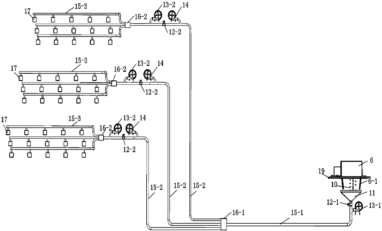
[0038] Embodiment 1 of the ice storage air-conditioning system based on pneumatic transmission and distribution of the present invention is as follows: figure 1 As shown, it includes an ice making and ice storage device, a connection device 11 , a channel valve 12 , a blower 13 , an exhaust fan 14 , a transmission pipe 15 , a pipe reverser 16 , and an air conditioner terminal device 17 .

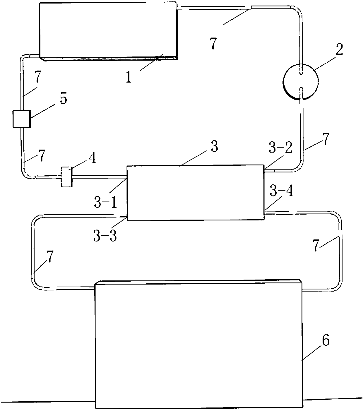
[0039] The ice-making and ice-storage device is composed of a condenser 1, a compressor 2, an evaporator 3, an expansion valve 4, a dry filter 5, a refrigerator 6, a liquid refrigerant pipeline 7, and a platform 19, such as image 3 As shown, the outlet of the condenser 1 is connected to the inlet of the drier filter 5 through the liquid refrigerant pipeline 7, the outlet of the drier filter 5 is connected to the evaporator inlet I3-1 through the liquid refrigerant pipeline 7, and the outlet ...

Embodiment 2

[0042] Embodiment 2: It is suitable for full ice storage and distributed air conditioning systems.

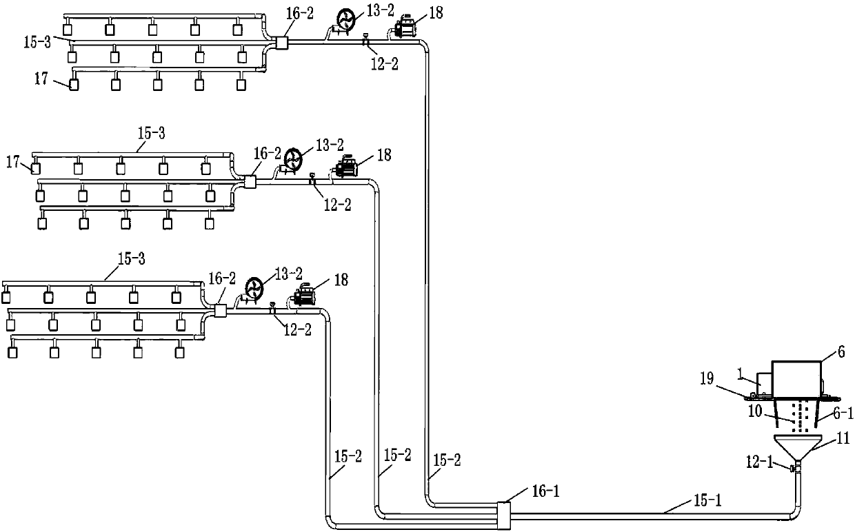
[0043] Embodiment 2 of the ice storage air-conditioning system based on pneumatic transmission and distribution of the present invention is as follows: figure 2 As shown, it includes an ice making and ice storage device, a connecting device 11 , a passage valve 12 , a transmission pipe 15 , a pipe reverser 16 , an air conditioner terminal device 17 , and a vacuum pump 18 .

[0044] The difference between the power unit of embodiment 2 and embodiment 1 is the power unit. In the embodiment, the transmission power between the first channel valve 12-1 and the second channel valve 12-2 is the first air blower 13-1, exhaust fan 14 The two parts are used together, the structure is complicated, and the convenience of operation is reduced. In the second embodiment, the vacuum pump 18 is used to replace the first blower 13-1 and the exhaust fan 14, which is more practical.

Embodiment 3

[0045] Embodiment 3: It is suitable for full ice storage, centralized or semi-centralized air conditioning systems.

[0046] Embodiment 3 of the ice storage air-conditioning system based on pneumatic transmission and distribution of the present invention is as follows: Figure 8 As shown, it consists of ice making and ice storage device, connection device 11, channel valve 12, transmission pipeline 15, vacuum pump 18, heat exchanger 20, heat exchanger inlet pipe 21, heat exchanger outlet pipe 22, water collector 23, Water divider 24, Y type filter 25 form.

[0047] The ice-making and ice-storage device and the connection device 11 are exactly the same as those in Embodiment 1. The ice cubes 10 in the storage refrigerator 6 enter the transmission pipeline 15 through the connection device 11, and a channel valve 12 is installed at the entrance of the transmission pipeline 15. , the ice cube 10 is delivered to the passage valve 12, and the passage valve 12 is opened. After the i...


PUM


Abstract

The invention provides an ice storage air conditioning system based on pneumatic transport and distribution. The ice storage air conditioning system is composed of an ice making and storage device, aconnecting device, a channel valve, air blowers, exhaust fans, transport pipelines, a pipeline reverser and an air conditioning terminal device. The ice storage air conditioning system has the beneficial effects that the system is combined with a solar photovoltaic power generation system, electricity generated by solar energy maintains operation of a central air conditioning in a non-ice storagestate, disturbance to a power grid during peak-load hours is reduced, and more energy is saved. The air conditioning system adopts the pneumatic transport and distribution mode, transport and distribution energy consumption is small, and the starting speed is high. Compared with a traditional water pump, the building energy consumption can be reduced by at least 15%. In the energy-saving reconstruction process of a building, the applicability is high, the capacity of a refrigerating unit is smaller, the service life is longer, the refrigerating capacity is improved by 30-50%, and the operationcost is reduced by 60%.

Description

technical field [0001] The invention relates to the field of air-conditioning, in particular to an ice-storage air-conditioning system based on pneumatic transmission and distribution, which is capable of rapid transmission and has low cooling loss. Background technique [0002] Ice-storage air-conditioning is to use the low-load power at night to make ice and store it in the ice-storage device. During the day, the ice melts to release the stored cold energy, reducing the power load of air-conditioning and the installed capacity of the air-conditioning system during the peak hours of the power grid. It represents the world today. The development direction of central air conditioning. The ice cubes produced by the existing ice storage air conditioners directly absorb the heat of the liquid refrigerant, so that the cooled liquid refrigerant flows back into the room, thereby absorbing the heat of the room, instead of sending ice cubes into the room to directly cool the room, wh...

Claims


Application Information

Patent Timeline
Patent Type & Authority Applications(China)
IPC IPC(8): F24F5/00F25B43/00
CPCF24F5/0017F25B43/003Y02E60/14
Inventor 姚万祥李赛男潘国华张春晓郑明静许春峰
Owner TIANJIN CHENGJIAN UNIV
Why Eureka
Try Eureka