
Remote horizontal vibration monitoring system

A monitoring system and horizontal technology, applied in the field of remote horizontal vibration monitoring system, can solve the problems of inaccurate prediction results, untimely prediction of dangerous buildings, threats to residents' lives and property, etc., and achieve the effect of preventing false alarms and intuitive real-time monitoring

Inactive Publication Date: 2018-05-11
苏州合衡动电子科技有限公司
View PDF2 Cites 1 Cited by
  • Summary
  • Abstract
  • Description
  • Claims
  • Application Information

AI Technical Summary

Problems solved by technology

[0002] Existing natural disasters such as geological disasters, landslides, and building vibrations are generally predicted by the Earthquake Bureau on a large scale. The prediction results are not accurate enough, and cannot be specific to a single building. Timely prediction of dangerous buildings is likely to pose a threat to the lives and properties of residents, and there is no effective solution at present

Method used


Image

  • Remote horizontal vibration monitoring system
  • Remote horizontal vibration monitoring system

Examples


Embodiment 1

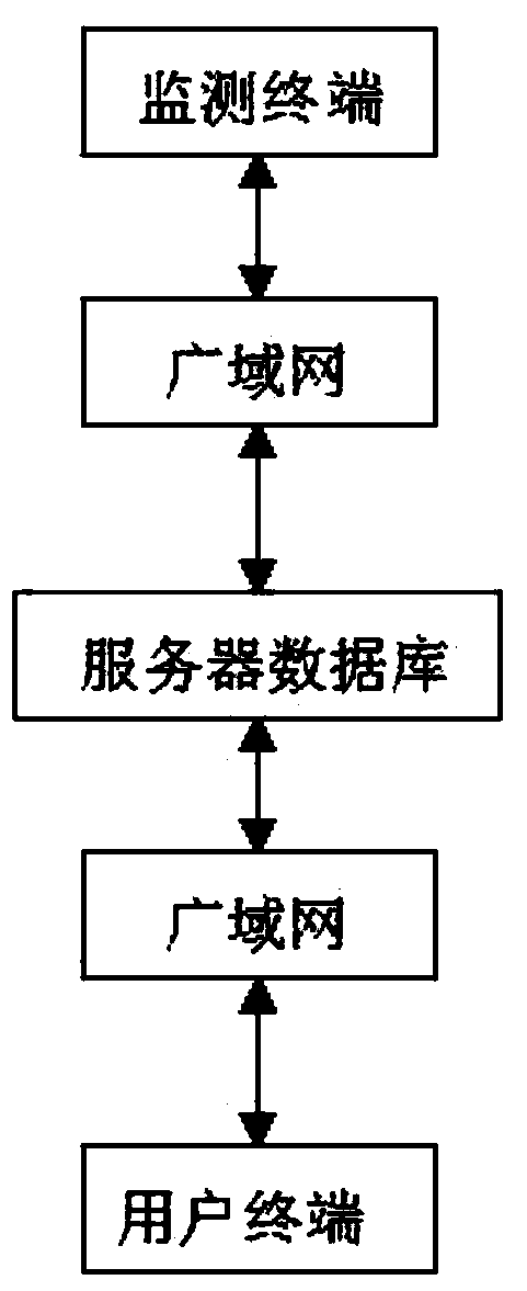
[0017] A remote horizontal vibration monitoring system, including a monitoring terminal for monitoring building tilt and vibration data, the monitoring terminal uploads the monitoring data to a server database in the cloud through the Internet of Things, and the server database is connected through a wide area network and not less than one The user terminal is connected in communication, and the user terminal receives the monitoring data of the server database through the wide area network;

[0018] The monitoring terminal includes two identical dual-axis inclination sensors, and the XY axes of the two dual-axis inclination sensors receive sine wave signals in time-sharing, and the sine wave signals pass through the dual-axis inclination sensors and are output by the monitoring end of the dual-axis sensors and enter the switch , to realize the cycle monitoring of two sensors, the sine wave signal enters the following amplifier to amplify the sine wave signal after passing throu...

Embodiment 2

[0020] The PWM module in the CPU generates a PWM square wave signal, which is converted into a sine wave signal by a narrowband filter and then enters the follower amplifier. After being processed by the follower amplifier, the sine wave signal is strengthened, and the strengthened sine wave signal enters the dual-axis tilt The next signal transmission is carried out in the sensor.

[0021] The present invention installs a sensor that can detect the inclination angle of an object on a building, a dam or a mountain, and converts the wave signal of the sensor into a specific offset angle value after further digital processing, and the inclination angle is uploaded to the cloud through the Internet of Things The server and the cloud server publish the information to the user terminal equipment (mobile phone). Since we have adopted a dual-sensor structure on the monitoring terminal and uploaded the measurement parameters of the two sensors to the server at the same time, this can e...


PUM


Abstract

The invention relates to the field of horizontal and vibration monitoring technologies, and in particular to a remote horizontal vibration monitoring system, including a monitoring terminal for monitoring building tilt and vibration data. The monitoring terminal uploads monitoring data to a cloud server database through the Internet of Things. The server database is communicatively connected withnot less than one user terminal through a wide area network. The user terminal receives the monitoring data of the server database through the wide area network. According to the invention, the monitoring terminal with a dual sensor structure is installed on a building, a dam or a mountain, electrical signals of the sensors are uploaded to the cloud server through the Internet of Things, and the cloud server publishes the information to the user terminal equipment (mobile phone), so that false alarms caused by the damage of the device can be effectively prevented. Therefore, a detected objectcan be monitored more effectively and intuitively in a convenient manner. The tilt of the building can be monitored intuitively in real time in a convenient manner.

Description

technical field [0001] The invention relates to the technical field of level and vibration monitoring, in particular to a remote level vibration monitoring system. Background technique [0002] Existing natural disasters such as geological disasters, landslides, and building vibrations are generally predicted by the Earthquake Bureau on a large scale. The prediction results are not accurate enough, and cannot be specific to a single building. When the building is aging or the foundation changes, it cannot Timely prediction of dangerous buildings is likely to bring threats to the lives and property of residents, and there is no effective solution at present. Contents of the invention [0003] The purpose of the present invention is to overcome the deficiencies in the prior art, and to provide a remote horizontal vibration monitoring system, by installing a sensor that can detect the inclination angle of an object on a building, a dam or a mountain, and further passing the w...

Claims


Application Information

Patent Timeline
IPC IPC(8): G01H3/12G08C17/02H04L29/08
CPCG01H3/12G08C17/02H04L67/10H04L67/12
Inventor 沈煜旻陈晓燕
Owner 苏州合衡动电子科技有限公司
Learn More