
Transformer and assembly method thereof

A technology for transformers and adapters, which is applied in transformer/inductor cores, transformer/inductor components, and inductor/transformer/magnet manufacturing, etc., can solve the problems of Y capacitor leakage current, increased adapter cost, and high Y capacitor cost. , to achieve the effect of improving safety performance, reducing volume and cost

Active Publication Date: 2018-05-11
HUAWEI MACHINERY
View PDF2 Cites 2 Cited by
  • Summary
  • Abstract
  • Description
  • Claims
  • Application Information

AI Technical Summary

Problems solved by technology

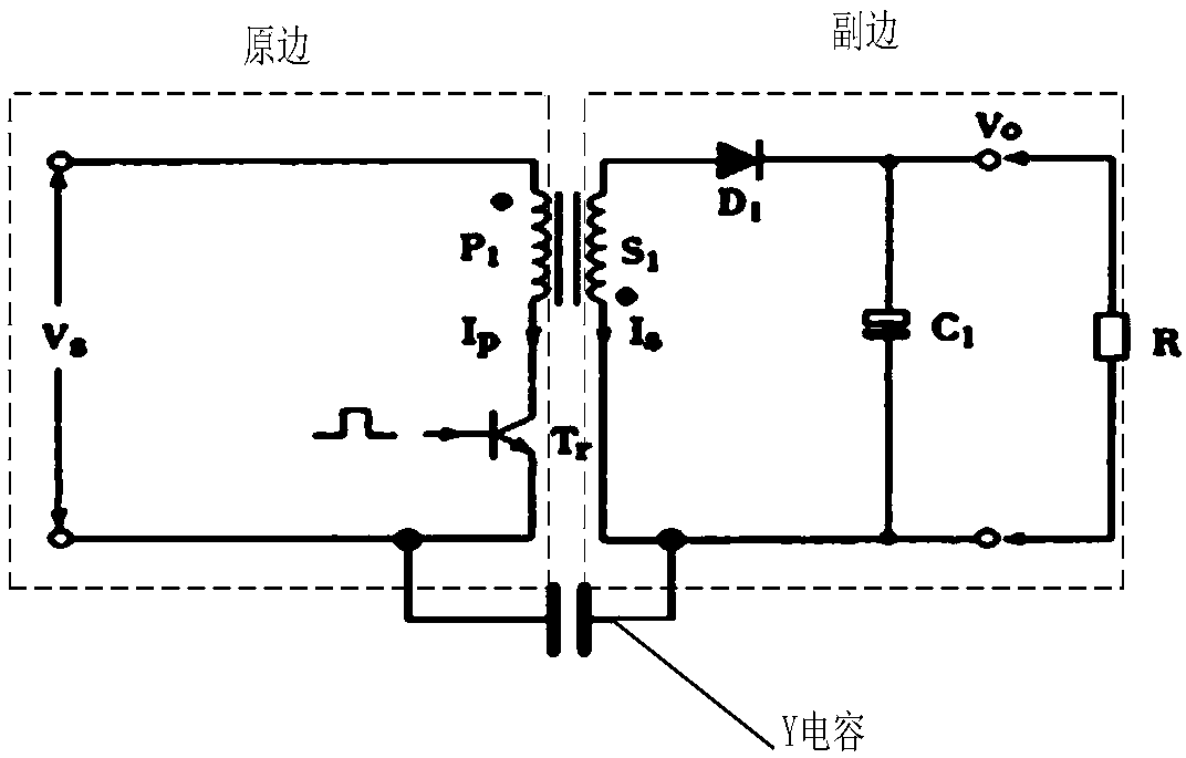
[0005] However, the technical solution of introducing Y capacitors to solve the EMC problem has the following disadvantages: the imported Y capacitors are large in size and occupy a large space, which is not conducive to the miniaturization of the adapter; The cost of the Y capacitor is higher, which increases the cost of the adapter;

Method used


Image

  • Transformer and assembly method thereof
  • Transformer and assembly method thereof
  • Transformer and assembly method thereof

Examples


Embodiment Construction

[0077] The following will clearly and completely describe the technical solutions in the embodiments of the present invention with reference to the accompanying drawings in the embodiments of the present invention. Obviously, the described embodiments are only some, not all, embodiments of the present invention. Based on the embodiments of the present invention, all other embodiments obtained by persons of ordinary skill in the art without making creative efforts belong to the protection scope of the present invention.

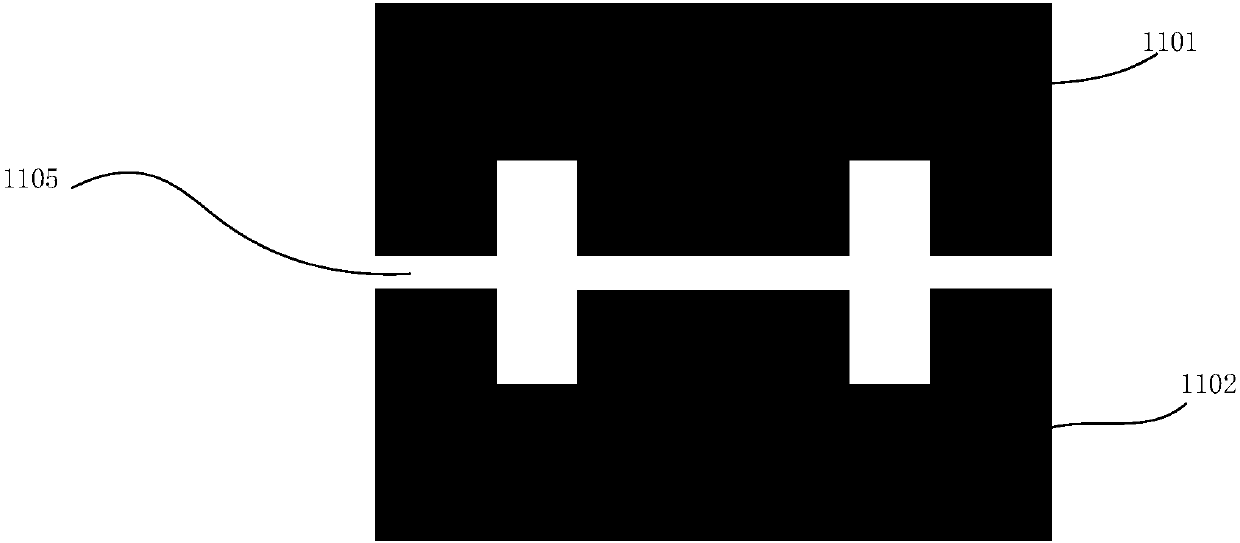
[0078]An embodiment of the present invention provides a transformer, which includes: a magnetic core, a primary power winding, a secondary power winding, and a shielding winding; the magnetic core includes an upper magnetic core and a lower magnetic core, and the upper magnetic core and the lower magnetic core The magnetic cores are interlocked with each other, the above-mentioned upper magnetic core and the above-mentioned lower magnetic core each have at leas...


PUM

PropertyMeasurementUnit
relative permittivityaaaaaaaaaa

Abstract

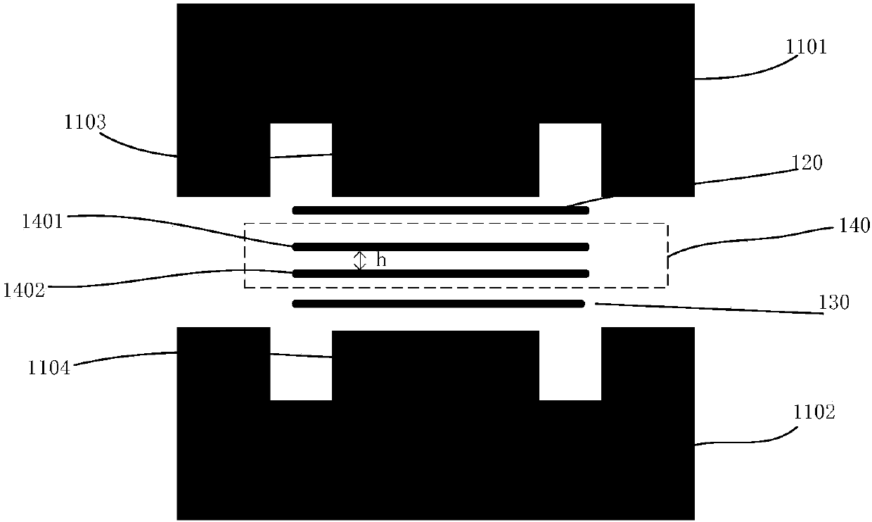
The invention provides a transformer, which comprises a magnetic core, a primary power winding, a secondary power winding and a shielding winding, wherein the magnetic core comprises an upper magneticcore and a lower magnetic core; a wrapping post of the upper magnetic core is matched with the wrapping post of the lower magnetic core in a manner of position correspondence to form a magnetic coreshaft column; each magnetic core shaft column is sleeved with the primary power winding, the secondary power winding and the shielding winding; the shielding winding comprises a primary shielding winding and a secondary shielding winding; and the primary shielding winding and the secondary shielding winding are stacked up and down and the spacing distance is h. According to the transformer, a lowresistance return channel is provided for primary noise coupled to a secondary side through adding the shielding winding and replacing a crossover Y capacitor to solve the problem of EMC; the cost andthe volume of the transformer can be reduced; and a hidden danger of leakage current is avoided.

Description

technical field [0001] The invention relates to the field of electrical engineering, in particular to a transformer and a manufacturing method thereof. Background technique [0002] With the rapid development of mobile Internet and terminal technology, the popularity of portable electronic products including communication terminals and wearable devices. People's requirements for the miniaturization, cost and safety of adapters for charging portable electronic products are also getting higher and higher. [0003] Most adapters use flyback converters to realize ACDC conversion. The transformer is one of the key components of the converter; however, the current applied transformers are mainly traditional wire-wound transformers, which are large in size, not conducive to miniaturization, and have complex internal structures and high processing costs. [0004] The parasitic parameters between the windings of traditional wire-wound transformers are large and difficult to control...

Claims


Application Information

Patent Timeline
Patent Type & Authority Applications(China)
IPC IPC(8): H01F27/24H01F27/28H01F27/36H01F27/30H01F41/02
CPCH01F27/24H01F27/2804H01F27/289H01F27/306H01F41/02
Inventor 余鹏
Owner HUAWEI MACHINERY
Learn More