Power cable pay-off device

A technology for power cables and pay-off devices, which is applied to cable laying equipment and other directions, can solve the problems of troublesome operation, non-straight hard cables, laborious cutting speed, etc., and achieve the effects of convenient pay-off construction, convenient operation and reliable operation.

Pending Publication Date: 2018-05-11
STATE GRID CORP OF CHINA +1
View PDF0 Cites 8 Cited by
  • Summary
  • Abstract
  • Description
  • Claims
  • Application Information

AI Technical Summary

Problems solved by technology

Since there is no dedicated fast power cable pay-off device, it is not only troublesome to operate, time-consuming and labor-intensive, but also the hard cable pulled out is not straight, and it is not easy to use because it is not known how long the cable is...

Method used


Image

  • Power cable pay-off device
  • Power cable pay-off device
  • Power cable pay-off device

Examples


Embodiment Construction

[0027] The present invention will be described in further detail below in conjunction with the accompanying drawings.

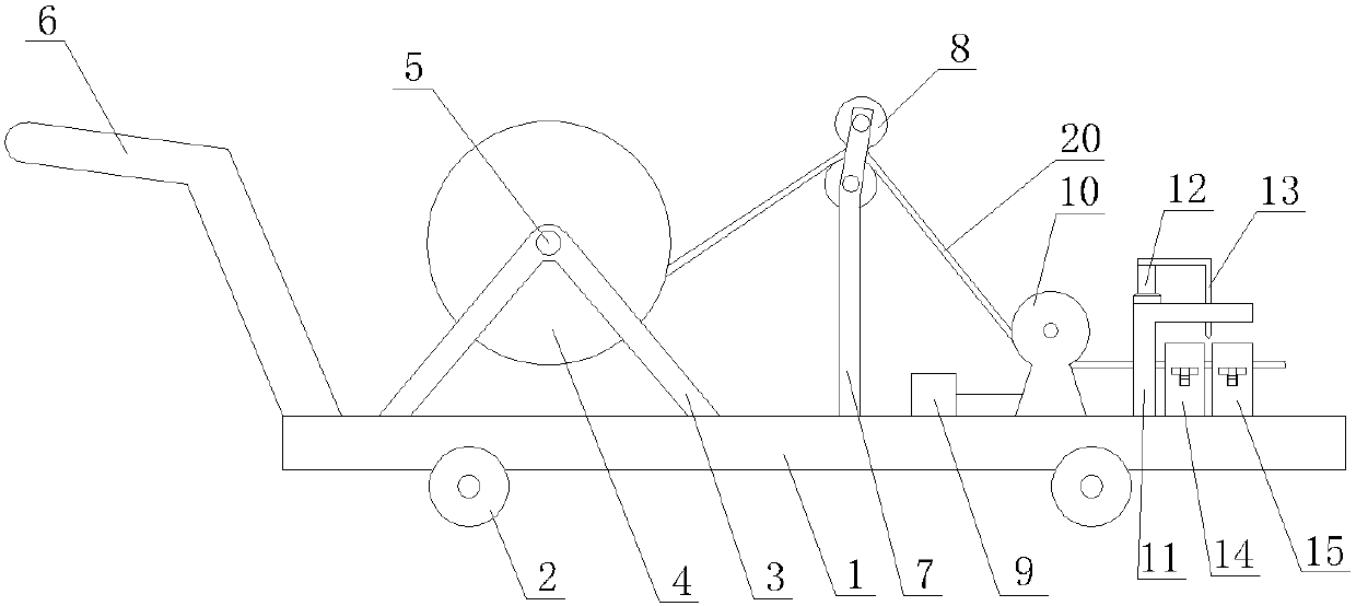
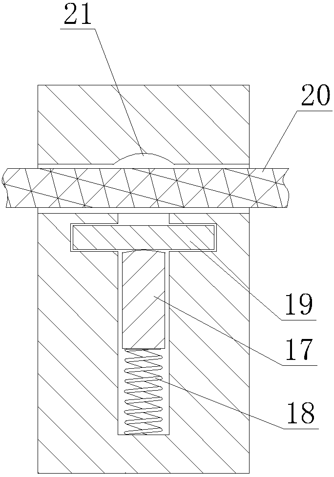
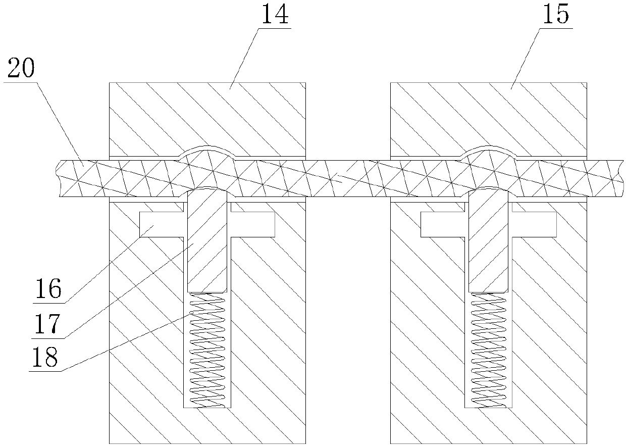
[0028] as attached Figure 1-7 As shown, a power cable release device includes a frame 1, a first bracket 3 fixed on the frame 1 in sequence, a second bracket 7 and a third bracket 10, and is connected to the first bracket 3 through a rotating shaft 5 in rotation. The cable reel 4, the tension wheel group 8 that is rotatably connected to the second support 7, the wire passing shaft that is rotatably connected to the 3rd support 10 and the walking wheel 2 that is arranged on the frame 1 below; the 3rd support 10 It includes a support plate fixed on the frame 1, two side plates 101 fixed on the support plate, a central shaft 102 fixedly connected between the two side plates 101, a sensor probe 25 arranged inside the side plate 101 and a set Connect the counter 9 of the sensor probe 25 on the frame 1; the wire passing shaft includes the passing wire shaft body ...


PUM


Abstract

The invention discloses a power cable pay-off device, comprising a frame, a first support rack, a second support rack, a third support rack, a cable drum, a tensioning wheel set, a wire passing shaftand a walking wheel; the first support rack, the second support rack and the third support rack are orderly fixed on the frame; the cable drum is connected onto the first support rack in a rotating manner through a rotating shaft, the tensioning wheel set is connected onto the second support rack in a rotating manner, the wire passing shaft is connected to the third support rack in a rotating manner, and the walking wheel is arranged below the frame; the third support rack includes a supporting plate fixed on the frame, two side plates fixed on the supporting board, a central shaft fixedly connected between the two side plates, sensor probes arranged inside the side plates, and a counter disposed on the frame and connected with the sensor probes. The power cable pay-off device is characterized by simple structure, convenient operation and reliable operation; the power cable pay-off device can be widely applied in power cable laying operation, cable pay-off construction can be greatly facilitated, construction efficiency can be effectively improved, and labor intensity of construction workers can be lowered.

Description

technical field [0001] The invention relates to a power cable releaser. Background technique [0002] With the development of the power grid, the amount of cables in various distribution networks continues to increase, but the quality and efficiency of cable laying and laying have not been effectively resolved. Finally, it is necessary to use a crane to lift it for laying. This operation method not only requires great physical strength of the construction personnel, but also easily increases the torque of the cable itself or damages the cable insulation layer, thereby bringing hidden dangers to the safety of power supply in the future. The power supply line is mainly composed of various power control devices connected by various power supply cables. Among them, various power supply cables are also erected in the power control equipment, and such power supply cables can be roughly divided into hard cables and flexible cables in terms of material hardness. Soft cable means t...

Claims


Application Information

Patent Timeline
IPC IPC(8): H02G1/06
CPCH02G1/06
Inventor 董韬巩保峰苗俊杰武光华杨海运
Owner STATE GRID CORP OF CHINA
Why Eureka
Try Eureka