Construction auxiliary pay-off device of power supply station

The technology of a pay-off device and power supply station is applied in the directions of transportation and packaging, thin material handling, and filamentary material transportation. , The effect of reliable operation and convenient operation

Active Publication Date: 2018-04-20
国网河北省电力有限公司安平县供电分公司 +1
View PDF6 Cites 2 Cited by
  • Summary
  • Abstract
  • Description
  • Claims
  • Application Information

AI Technical Summary

Problems solved by technology

At present, during the cable laying and laying construction process, after the cable is transported to the site, it needs to be laid by a crane. This operation method not only requires great physical strength of the construction personnel, but also easily increases the torque of the cable itself or damages the cable. Insulation layer, which will bring hidden dangers to the safety of power supply in the future
The existing pay-off vehicles mainly have the following problems when they are in use: most of the existing pay-off vehicles only play a simple supporting role for the coil, and it is still necessary to manually pull and release the cables when performing operations. Due to the heavy weight of the cables, The labor intensity of the operator is high, and the method of manually pulling and releasing the cable can only be operated by the experience of the operator, the accuracy of the cable is low, or other personnel are required to cooperate with the operation, and the work efficiency is low; The force is large, and the pay-off car is often pulled down, or in order to prevent the pay-off car from being pulled down, other operators are required to assist
At present, the common pay-offs on the market are generally large in size and very inconvenient to carry. For some special working environments such as inconvenient transportation or small work areas, it is very difficult to implement the pay-off work. A pay-off with a small space, but when the pay-off is small, it cannot meet the working conditions of a large cable diameter or a long cable length

Method used


Image

  • Construction auxiliary pay-off device of power supply station
  • Construction auxiliary pay-off device of power supply station
  • Construction auxiliary pay-off device of power supply station

Examples


Embodiment Construction

[0022] The present invention will be described in further detail below in conjunction with the accompanying drawings.

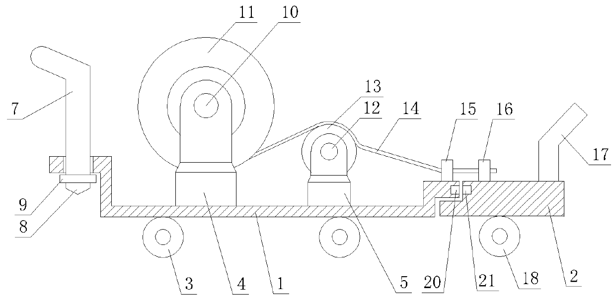
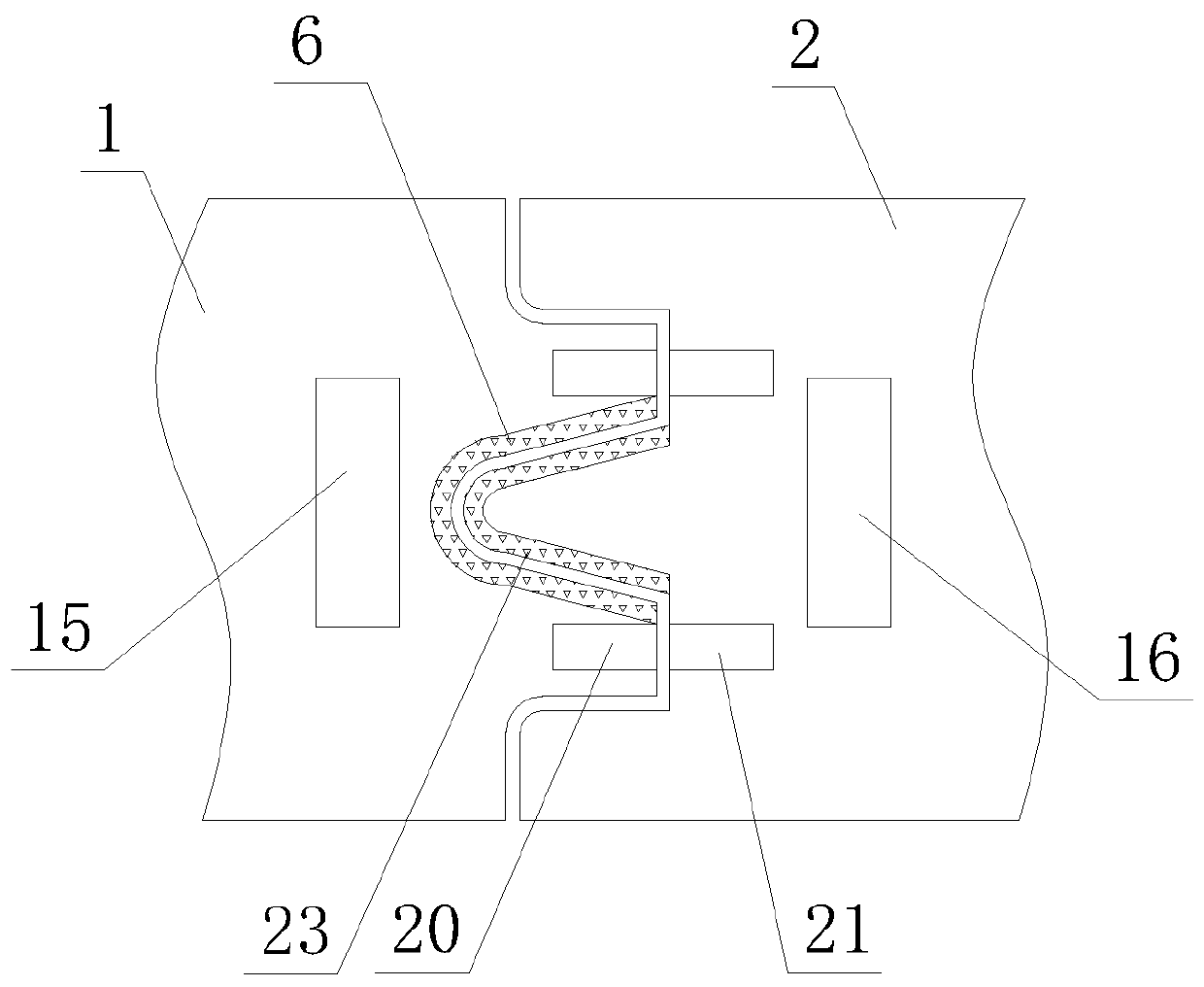
[0023] as attached Figure 1-3 As shown, a power supply station construction auxiliary pay-off device includes a front carrying vehicle and a pay-off vehicle that is buckled with the rear of the front carrying vehicle; the front carrying vehicle includes a carrying frame 1, the lower end of which is fixedly connected to the carrying The first telescopic support rod 4 and the second telescopic support rod 5 on the vehicle frame 1, the first central shaft 10 fixed on the upper part of the first telescopic support rod 4, the cable reel 11 that is rotatably sleeved on the outside of the first central shaft 10, The second central shaft 12 fixed on the top of the second telescopic support rod 5 , the guide wheel 13 that is rotatably sleeved outside the second central shaft 12 , and the load-carrying road wheel 3 arranged under the load-carrying frame 1 . The front...


PUM


Abstract

The invention discloses a construction auxiliary pay-off device of a power supply station. The construction auxiliary pay-off device comprises a front bearing vehicle and a pay-off vehicle in buckledfit with the tail of the front bearing vehicle. The front bearing vehicle comprises a bearing frame, a first telescopic supporting rod, a second telescopic supporting rod, a first center shaft fixed to the upper portion of the first telescopic supporting rod, a cable disc rotationally mounted on the outer portion of the first center shaft in a sleeving manner, a second center shaft fixed to the upper portion of the second telescopic supporting rod, a wire wheel rotationally mounted on the outer portion of the second center shaft in a sleeving manner, and bearing running wheels arranged below the bearing frame, wherein the lower end of the first telescopic supporting rod and the lower end of the second telescopic supporting rod are fixedly connected to the bearing frame. The construction auxiliary pay-off device has the advantages of being simple in structure, convenient to operate and reliable in operation and can be widely applied to power cable pavement construction, cable pay-off construction is greatly facilitated, construction efficiency is effectively improved, and the labor intensity of construction personnel is reduced.

Description

technical field [0001] The invention relates to the technical field of power tools for power supply stations, in particular to an auxiliary wire-laying device for power supply station construction. Background technique [0002] The power supply belongs to the dispatched agencies of the power company, which are distributed in various towns and towns, and mainly carry out line maintenance services, power outage services, meter reading, and electricity fee collection. In the construction process of transmission line erection, the traditional setting-out work is done manually by operators, which is time-consuming, labor-intensive and labor-intensive, which affects the construction progress. When performing line maintenance services, it is usually necessary to use a large number of wires and cables. In order to facilitate operation and improve work efficiency, an electric wire pay-off vehicle is often equipped at the same time. At present, during the cable laying and laying cons...

Claims


Application Information

Patent Timeline
Patent Type & Authority Applications(China)
IPC IPC(8): B65H49/30B65H61/00
CPCB65H49/30B65H61/00B65H2701/34
Inventor 张大伟
Owner 国网河北省电力有限公司安平县供电分公司
Why Eureka
Try Eureka