Micro-grid communication control method, device and system

A technology of communication control and micro-grid, applied in the field of micro-grid, can solve the hidden dangers of safety and stability of smart micro-grid, failure to read fault data and alarm information of micro-grid subsystems in time, and heavy workload

Active Publication Date: 2018-05-11
紫石能源有限公司
View PDF6 Cites 3 Cited by
  • Summary
  • Abstract
  • Description
  • Claims
  • Application Information

AI Technical Summary

Problems solved by technology

In practical applications, the smart microgrid uses wired network communication, and the communication link is a data network based on a wired Ethernet connection. Link disconnection failures often occur due to animals, man-made, or the environment, resulting in failure of the smart microgrid. The subsystem is separated from the parent system, and the smart microgrid loses the relevant data and alarm information of the collection point, which brings great hidden dangers to the safety and stability of the smart microgrid. The alarm frequency of the smart microgrid is also very high, which requires manual processing. Heavy workload
[0003] in addition, figure 1 In the existing smart micro-grid structure shown, the local database module of the micro-grid subsystem is associated with the local micro-server. The defect is that the data stored in the local database module is the data processed by the micro-grid data acquisition module, not the original data. When In the event of a link disconnection fault, the data stored in the local database module is not conducive to the analysis of the cause of the fault and the management of the microgrid due to non-original data
[0004] in addition, figure 1 In the existing smart microgrid structure shown, the microgrid subsystem is connected to the microgrid parent system using a wired network communication. When a physical fault occurs in the wired network, the microgrid parent system cannot read the fault data of the microgrid subsystem in time and Alarm information, which is not conducive to analyzing the cause of the fault and microgrid management

Method used


Image

  • Micro-grid communication control method, device and system
  • Micro-grid communication control method, device and system
  • Micro-grid communication control method, device and system

Examples


Embodiment Construction

[0024] In order to make the purpose, technical solutions and advantages of the embodiments of the present invention clearer, the technical solutions in the embodiments of the present invention will be clearly described below in conjunction with the accompanying drawings in the embodiments of the present invention. Obviously, the described embodiments are the Some, but not all, embodiments are invented.

[0025] It should be noted that, in this article, "first" and "second" are only used to distinguish the same names, rather than implying the relationship or order between these names.

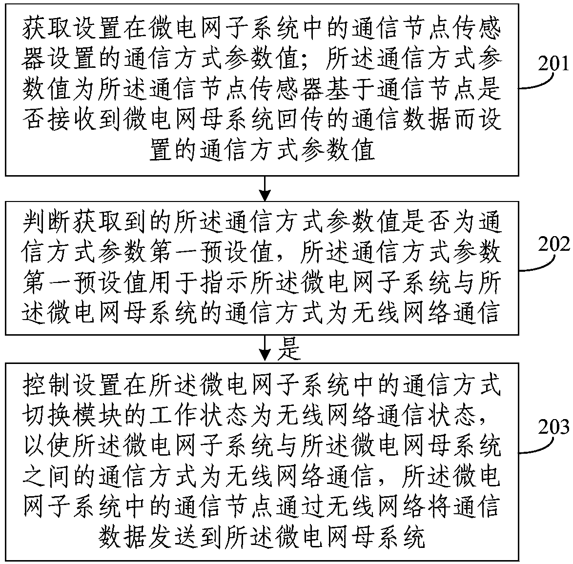
[0026] Such as figure 2 As shown, this embodiment discloses a microgrid communication control method, which may include the following steps 201 to 203:

[0027] 201. Obtain the communication mode parameter value set by the communication node sensor set in the microgrid subsystem; the communication mode parameter value is set by the communication node sensor based on whether the communication n...


PUM


Abstract

The invention discloses a micro-grid communication control method, device and system. The method comprises the steps of: obtaining a communication mode parameter value set by a communication node sensor arranged in a micro-grid sub-system; judging whether the communication mode parameter value is a first communication mode parameter pre-set value or not, wherein the first communication mode parameter pre-set value is used for indicating that the communication mode of the micro-grid sub-system and a micro-grid parent-system is wireless network communication; and if so, controlling the working state of a communication mode switching module arranged in the micro-grid sub-system to a wireless network communication state, so that the communication mode of the micro-grid sub-system and the micro-grid parent-system is wireless network communication, wherein a communication node in the micro-grid sub-system sends communication data to the micro-grid parent-system through a wireless network. According to the micro-grid communication control method, device and system disclosed by the invention, whether a wired network fails or not is determined through the communication mode parameter value;furthermore, uninterrupted communication between the micro-grid sub-system and the micro-grid parent-system during the fault period of the wired network can be ensured; and the offline problem of themicro-grid sub-system is solved.

Description

technical field [0001] The present invention relates to the technical field of micro-grids, in particular to a micro-grid communication control method, device and system. Background technique [0002] The smart microgrid consists of a mother system and multiple subsystems, each subsystem communicates with the mother system, figure 1 It is a schematic diagram of the structure of the existing smart microgrid, figure 1 Only one subsystem is shown in the figure 1 The structure of the subsystems shown is similar, and the connections between other subsystems and the parent system are the same as figure 1 The shown subsystems are connected in the same way as the parent system, so the structures of other subsystems and the connection methods with the parent system are not shown again. In practical applications, the smart microgrid uses wired network communication, and the communication link is based on a data network connected by wired Ethernet. Link disconnection failures often ...

Claims


Application Information

Patent Timeline
Patent Type & Authority Applications(China)
IPC IPC(8): H04L12/24H02J13/00
CPCH02J13/0013H04L41/0663
Inventor 韩燕川刘松利赵昂丁建
Owner 紫石能源有限公司
Why Eureka
Try Eureka