Relay transfer method and apparatus, terminal and base station
A transfer method and base station technology, applied in the communication field, can solve problems such as service interruption, and achieve the effect of improving user experience
- Summary
- Abstract
- Description
- Claims
- Application Information
AI Technical Summary
Problems solved by technology
Method used
Image
Examples
Embodiment 1
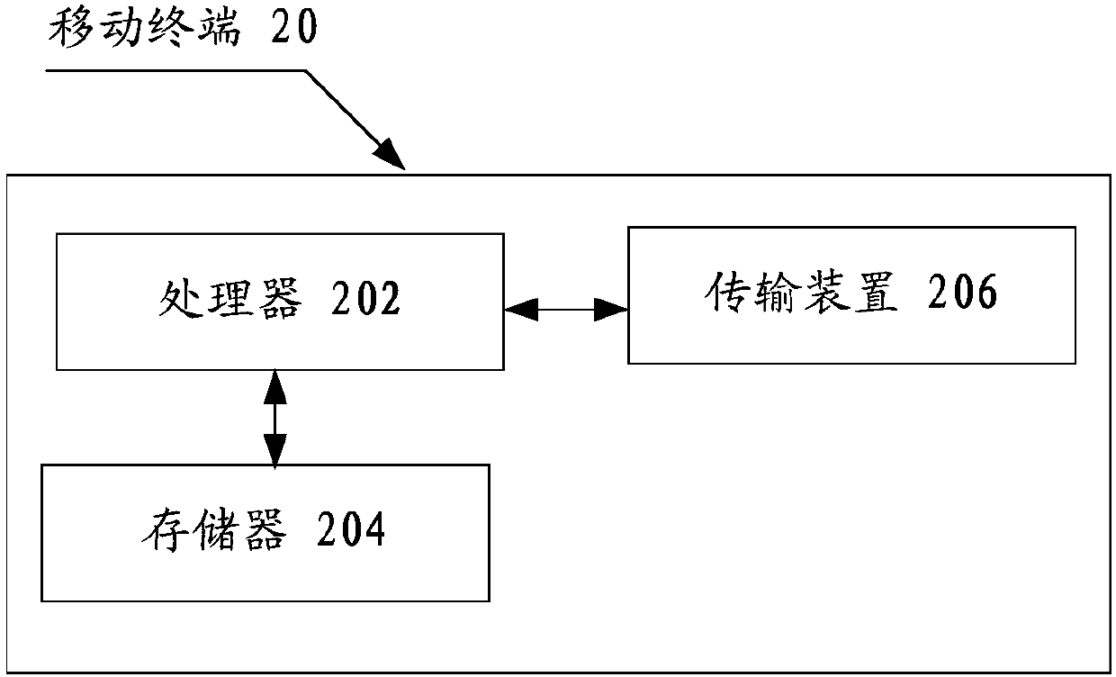
[0058] The method embodiment provided in Embodiment 1 of the present application may be executed in a mobile terminal, a computer terminal, or a similar computing device. Taking running on a mobile terminal as an example, figure 2 It is a hardware structure block diagram of a mobile terminal of a relay transfer method according to an embodiment of the present invention. Such as figure 2 As shown, the mobile terminal 20 may include one or more (only one is shown in the figure) processor 202 (the processor 202 may include but not limited to a processing device such as a microprocessor MCU or a programmable logic device FPGA, etc.), for A memory 204 for storing data, and a transmission device 206 for communication functions. Those of ordinary skill in the art can understand that, figure 2 The shown structure is only for illustration, and it does not limit the structure of the above-mentioned electronic device. For example, mobile terminal 20 may also include figure 2 mor...
Embodiment 2
[0078] In this embodiment, a relay transfer device, a base station, and a terminal are also provided, which are used to implement the above embodiments and preferred implementation modes, and those that have already been described will not be repeated. As used below, the term "module" may be a combination of software and / or hardware that realizes a predetermined function. Although the devices described in the following embodiments are preferably implemented in software, implementations in hardware, or a combination of software and hardware are also possible and contemplated.
[0079] Figure 4 is a structural block diagram of a relay transfer device according to an embodiment of the present invention, such as Figure 4 As shown, the device includes:
[0080] A determining module 40, configured to determine that the remote user equipment UE switches from performing path relay through the first relay device to performing path relay through the second relay device;
[0081] Th...
Embodiment 3
[0098] This embodiment is an optional embodiment according to the present invention, and is used to describe the application in detail in combination with specific scenarios:
[0099] This embodiment proposes a service continuity method and device in a relay network, including:
[0100] When the remote UE performs path switching between relay UE1 and relay UE2, relay UE3 and eNB1, where the serving base stations of relay UE1 and relay UE2 are the same, and the serving base station of relay UE3 is eNB1,
[0101] The remote UE performs RLC reestablishment and PDCP data recovery operations.
[0102] When the remote UE performs path switching between relay UE1 and relay UE2, relay UE3 and eNB1, where the serving base stations of relay UE1 and relay UE2 are different, and the serving base station of relay UE3 is different from eNB1,
[0103] The remote UE performs RLC re-establishment and PDCP re-establishment operations.
[0104] When the path of the remote UE is switched from a r...
PUM
 Abstract
Description
Claims
Application Information
 - R&D
- Intellectual Property
- Life Sciences
- Materials
- Tech Scout
- Unparalleled Data Quality
- Higher Quality Content
- 60% Fewer Hallucinations
Browse by: Latest US Patents, China's latest patents, Technical Efficacy Thesaurus, Application Domain, Technology Topic, Popular Technical Reports.
© 2025 PatSnap. All rights reserved.Legal|Privacy policy|Modern Slavery Act Transparency Statement|Sitemap|About US| Contact US: help@patsnap.com


