Eureka AIR delivers breakthrough ideas for toughest innovation challenges, trusted by R&D personnel around the world.

Vehicle sailing stop control method and control device

A technology for stopping control and vehicles, applied in control devices, road vehicle drive control systems, transmissions, etc., can solve problems such as time lag, and achieve the effect of shortening time lag

Active Publication Date: 2018-05-11
JATCO LTD
View PDF9 Cites 0 Cited by
  • Summary
  • Abstract
  • Description
  • Claims
  • Application Information

AI Technical Summary

Problems solved by technology

Therefore, there is a problem that, when the coast stop control is withdrawn and the coasting running is returned to normal running, the flow rate that can be ensured for engaging the forward clutch decreases, and a time lag occurs until the forward clutch enters the power transmission state.

Method used


Image

  • Vehicle sailing stop control method and control device
  • Vehicle sailing stop control method and control device
  • Vehicle sailing stop control method and control device

Examples


Embodiment 1

[0022] First, the configuration will be described.

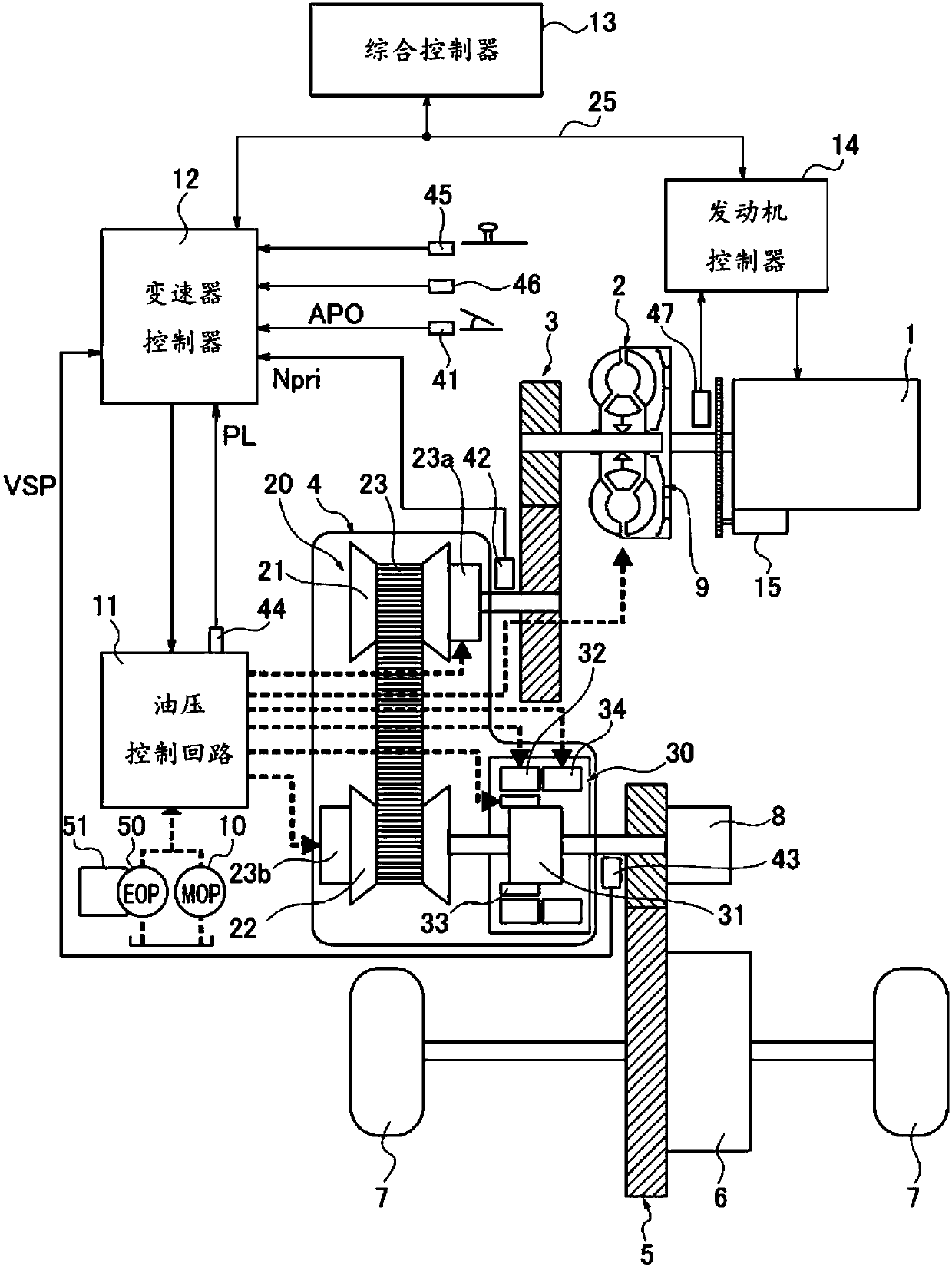
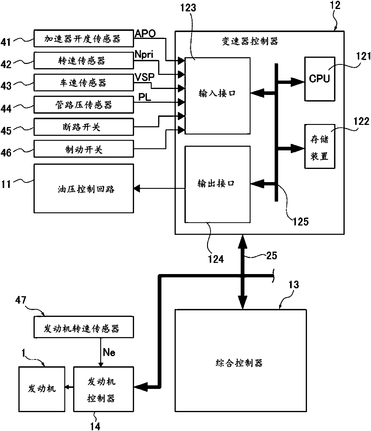
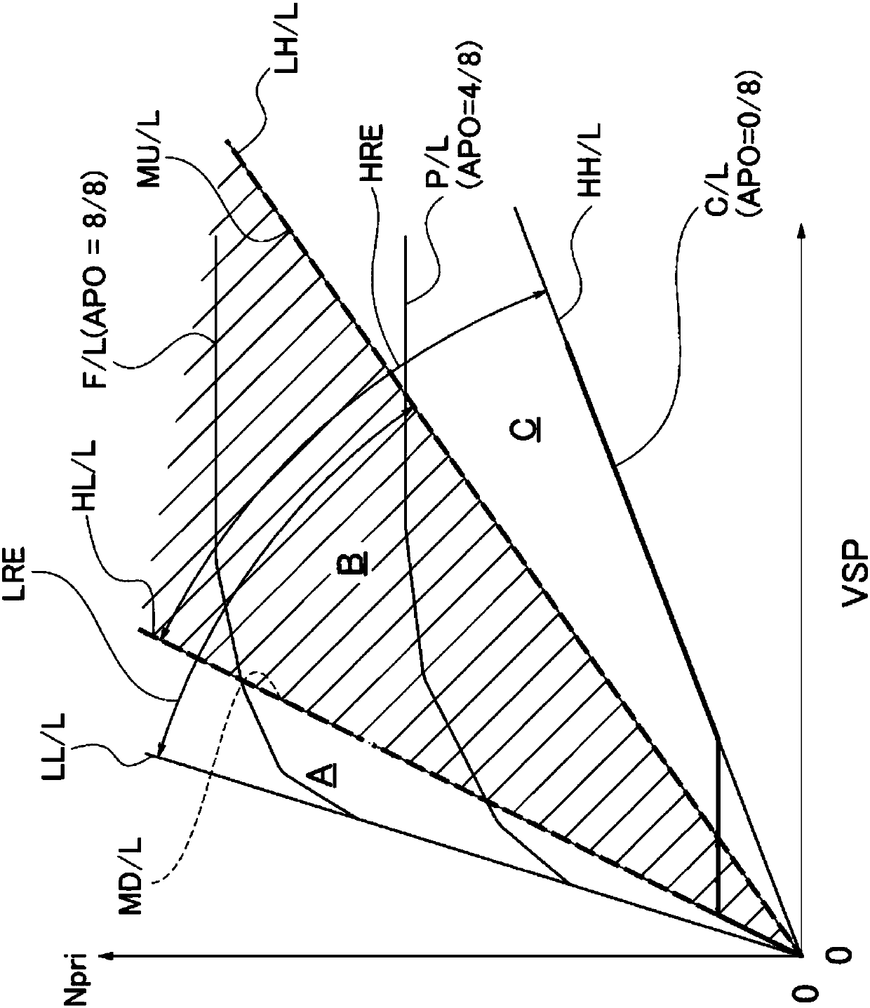
[0023] The coast stop control method and control device of Embodiment 1 are applied to an engine vehicle equipped with a continuously variable transmission with an auxiliary transmission. Next, the configuration of the coast stop control device for the engine car of Embodiment 1 is divided into "overall system configuration", "shift control configuration based on shift map", "circuit configuration of hydraulic control system", and "coast stop control process". Composition" is explained.

[0024] "Overall system composition"

[0025] figure 1 shows the overall configuration of an engine vehicle equipped with a continuously variable transmission with auxiliary transmission to which the coast stop control device of the first embodiment is applied, figure 2 Indicates the internal configuration of the transmission controller. Below, based on figure 1 and figure 2 Describes the overall system configuration.

[0026] In ad...


PUM


Abstract

A vehicle is provided with: a drive system clutch (Fwd / C) disposed between the engine (1) and drive wheels (7); a torque converter (2) disposed between the drive system clutch (Fwd / C) and the engine (1) and equipped with a lock-up clutch (9), in which the magnitude of power transmission is controlled by hydraulic pressure; and an electric oil pump (50) capable of supplying hydraulic pressure whilethe engine (1) is stopped. Said engined car coasts as a result of sailing stop control in which, when a sailing stop travel condition is met, power transmission by the drive system clutch (Fwd / C) isblocked and the engine (1) is stopped. While coasting under sailing stop control, hydraulic pressure for putting the lock-up clutch (9) into a power-transmitting state is applied to the lock-up clutch(9).

Description

technical field [0001] The present invention relates to a coasting stop control method and control device for a vehicle coasting by stopping power transmission from a driving source for traveling to drive wheels and stopping the driving source for traveling. Background technique [0002] Conventionally, there is known a vehicle coast stop control device that cuts off the power transmission from the drive source for travel to the drive wheels, and when performing coast stop control that stops the drive source for travel, uses the forward clutch and the forward clutch provided on the power transmission path to All the lock-up clutches are in a disengaged state (for example, refer to Patent Document 1). [0003] However, in the conventional device, during coasting by coast stop control, the lock-up clutch is maintained in a clutch disengaged state in which the required flow rate is increased compared with the case where the clutch is maintained in an engaged state. Therefore, ...

Claims


Application Information

Patent Timeline
Patent Type & Authority Applications(China)
IPC IPC(8): F16H61/14F16H59/38
CPCY02T10/60F16H61/143B60Y2300/18066F16H61/702F16H61/662F16H2059/186B60W10/023B60W10/18B60W30/18054F16H59/38F16H61/14B60W2540/12B60W2710/0616F16H61/0028F16H61/0031F16H61/148
Inventor 河住拓郎中崎胜启西广义祐大塚征史太田雄介中野裕介
Owner JATCO LTD
Why Eureka
Eureka Blog
Learn More