Body-building vehicle braking device

A technology of a braking device and an exercise bike, applied in the braking field, can solve the problems of hurting the user's hand, inconvenient use, irreversible damage, etc., and achieve the effect of a simple structure

Active Publication Date: 2018-05-15
昆山亚新鸿运动器材有限公司
View PDF6 Cites 1 Cited by
  • Summary
  • Abstract
  • Description
  • Claims
  • Application Information

AI Technical Summary

Problems solved by technology

[0003] The exercise bike is to allow the bodybuilder to achieve the effect of exercise and fitness by overcoming the resistance brought by the flywheel with a certain quality during the pedaling process to simulate the riding feeling. And the frame beam of the rear seat tube, the transmission device and the brake device. The main components of the transmission device are the chain and the flywheel. At present, the brake device of the common exercise bike flywheel is mostly directly extruded and contacted by the friction component and the flywheel during braking, relying on friction The extrusion resistance and friction resistance between the components and the flywheel stop the flywheel; this type of braking method has the following defects: usually the flywheel has a large mass, and when the flywheel is to stop at a faster speed, the bodybuilder needs to use a larger The high pressing force makes the friction between the visual component and the flywheel extrusion contact, so the reaction force generated during the pressing process is very likely to hurt the user's hand, and it is inconvenient to use, and it is impossible to accurately control the impact of the friction component on the flywheel. The size of the resistance; secondly, only the friction component generates resistance during the whole braking process, and the long-term friction between it and the flywheel is likely to cause irreversible damage, which needs to be replaced regularly. If it is not replaced in time, it is easy to cause personal injury to the user during use

Method used


Image

  • Body-building vehicle braking device
  • Body-building vehicle braking device
  • Body-building vehicle braking device

Examples


Embodiment Construction

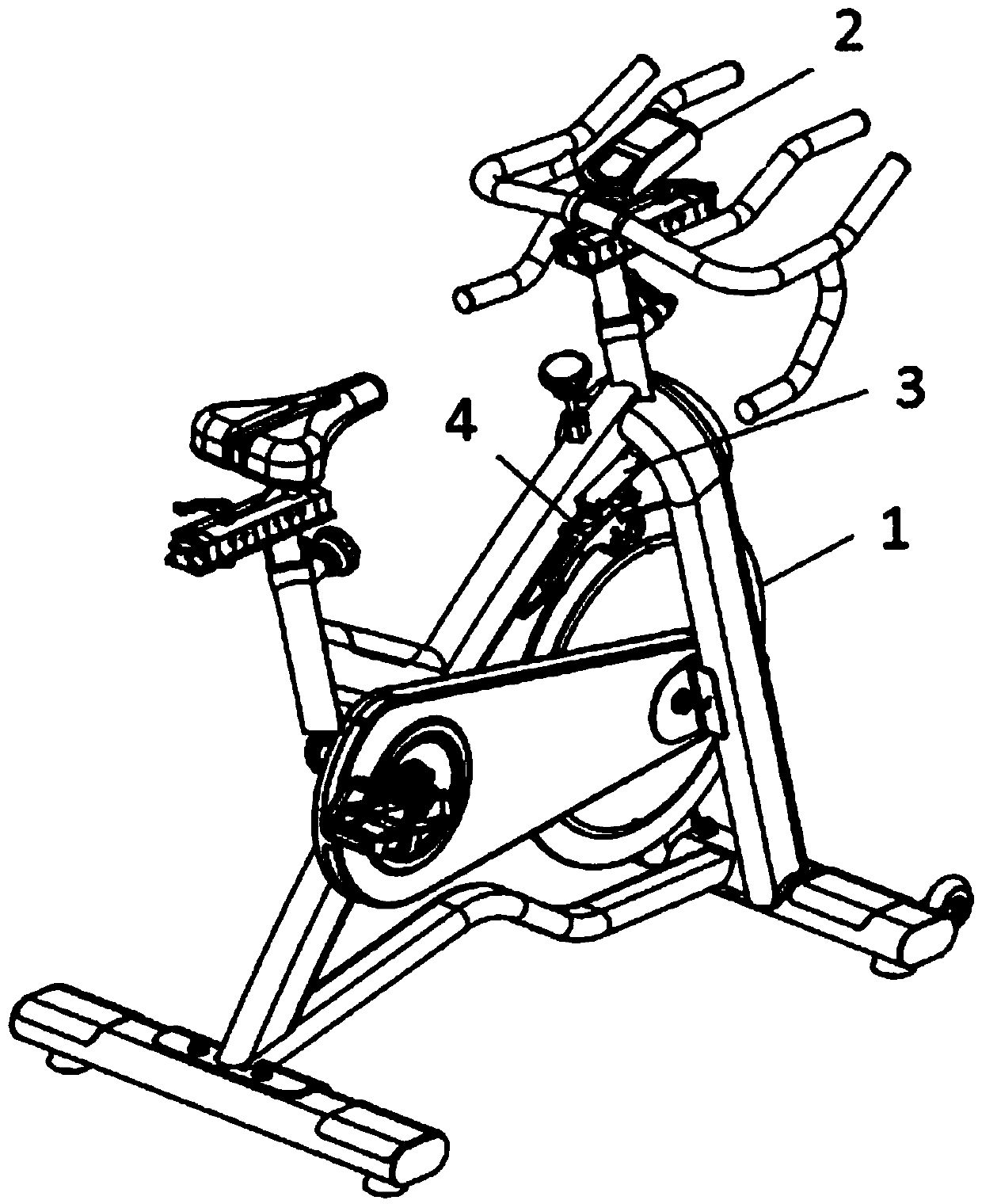
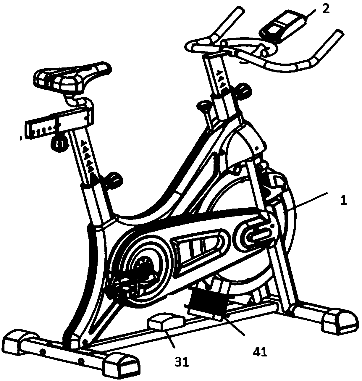
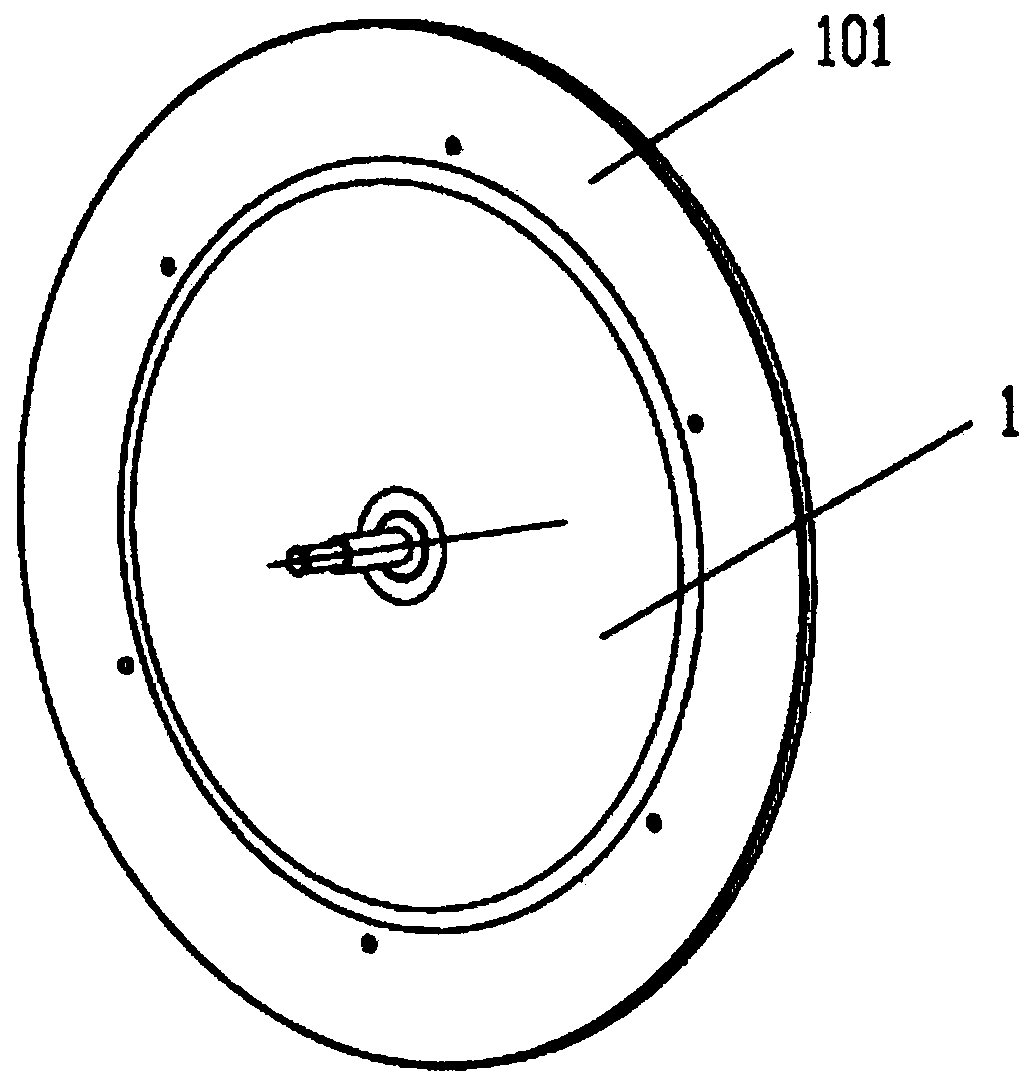
[0028] Please refer to figure 1 and Figure 5 Shown is a schematic diagram of the present invention. The present invention provides a brake device for exercise bikes, using the control device 2 to regulate the motor 301 so that the motor acts on the regulating part 302, thereby acting on the U-shaped groove 402 of the electromagnetic control base 401 in the electromagnetic control brake assembly 4 to act on the flywheel 1 To achieve the effect of braking, the structure is simple and easy to operate, and will not cause personal injury to the user.

[0029] Such as Figure 1 to Figure 5 As shown, the exercise bike brake device includes a control device 2, the control device 2 is a control device 2 with a panel; an adjustment assembly 3, the adjustment assembly 3 includes: a motor 301 and an adjustment component 302, and the control device 2 It is connected with the motor 301 in a wired or wireless manner, and the control of the motor 301 is controlled by a wired control devic...


PUM


Abstract

The invention discloses a body-building vehicle braking device. The device comprises a regulation device provided with a display screen and an electromagnetic control braking component which is arranged on the periphery of a flywheel and movably connected to a frame, wherein the regulation device is connected with the electromagnetic control braking component in a wired or wireless mode, a regulation part is installed on one side of the motor, and an outer ring of the flywheel is a metal ring coaxial with the flywheel; the electromagnetic control braking component comprises an electromagneticcontrol base movably connected to the frame, a U-shaped groove with the depth not smaller than the width of the metal ring is formed in the side, facing the flywheel, of the electromagnetic control base, and the U-shaped groove is internally provided with a magnet; the regulation device regulates the motor, acts on the regulation part and then acts on the electromagnetic control braking component,and the U-shaped groove of the electromagnetic control base acts on the flywheel. Accordingly, the motor is regulated by means of the regulation device to make the motor act on the regulation part, and the U-shaped groove acting on the electromagnetic control base in the electromagnetic control braking component acts on the flywheel, so that the barking effect is achieved, the structure is simple, and operation is convenient.

Description

technical field [0001] The invention relates to the technical field of braking, in particular to an electromagnetically controlled braking device for an exercise bike. Background technique [0002] With the development of society, people now pay more and more attention to health. Due to the influence of outdoor sports on the body during sports due to adverse factors such as weather and environment, indoor fitness is more and more popular among people. After overcoming the shortcomings of outdoor driving, it has become one of the fitness equipment for popular indoor sports because of its ease of learning and aerobic exercise that can exercise the whole body. [0003] The exercise bike is to allow the bodybuilder to achieve the effect of exercise and fitness by overcoming the resistance brought by the flywheel with a certain quality during the pedaling process to simulate the riding feeling. And the frame beam of the rear seat tube, the transmission device and the brake devic...

Claims


Application Information

Patent Timeline
IPC IPC(8): A63B22/06A63B21/005A63B24/00
CPCA63B21/0056A63B22/0605A63B24/0087
Inventor 吴东勇
Owner 昆山亚新鸿运动器材有限公司
Why Eureka
Try Eureka