Speed monitoring and braking device for vertical lifting equipment

A vertical lifting and speed monitoring technology, applied in the direction of hoisting devices, lifting frames, elevators, etc., can solve the problems of brake failure, increase the use cost, occupy a large space, etc., and achieve the effect of convenient and fast operation

Pending Publication Date: 2018-05-15
GUANGZHOU GUANGRI ELEVATOR IND
View PDF10 Cites 6 Cited by
  • Summary
  • Abstract
  • Description
  • Claims
  • Application Information

AI Technical Summary

Problems solved by technology

Yet the present inventor has found these problems at least after the speed monitoring of existing vertical lifting equipment and braking device have been deeply researched and analyzed: 1. With the increase of lifting height, the tension of tension The requirements are getting bigger and bigger, and the tension force is generally provided by the heavy hammer. The quality of the heavy hammer is designed to be larger and larger with the increase of the lifting height. At the same time, the steel wire rope, speed limiter and tensioning device The load is also getting bigger and bigger, which needs to be replaced more frequently or more expensive products are used, which greatly increases the cost of use; 2. When there is an extreme situation where the wire rope is completely disconnected, the safety gear lifting device that relies on the wire rope to provide power will It cannot work normally, which leads to braking failure; 3. The entire speed monitoring and braking device is arranged in the machine room and the hoistway, which requires a lot of extra space, which is not conducive to improving the utilization rate of the building

Method used


Image

  • Speed monitoring and braking device for vertical lifting equipment
  • Speed monitoring and braking device for vertical lifting equipment
  • Speed monitoring and braking device for vertical lifting equipment

Examples


Embodiment Construction

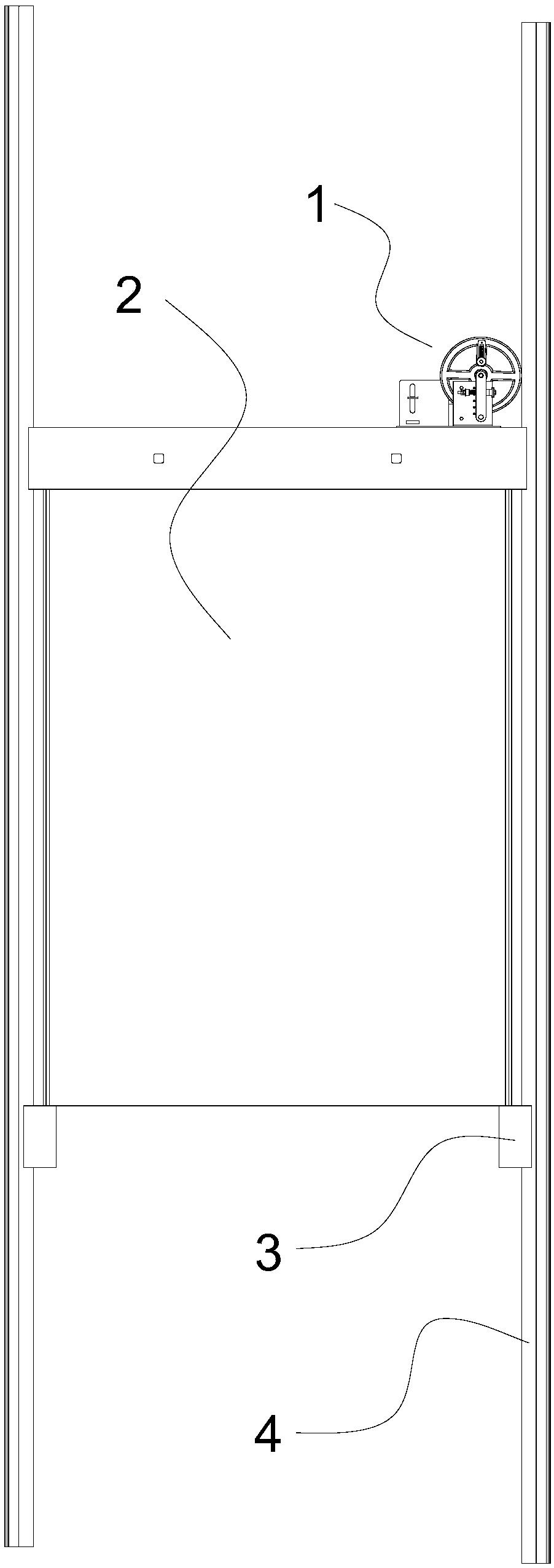
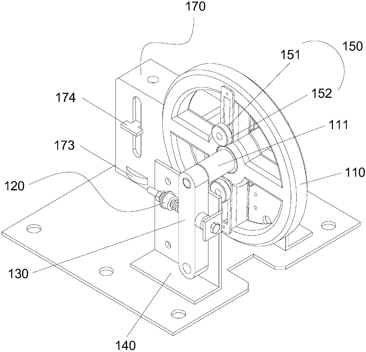
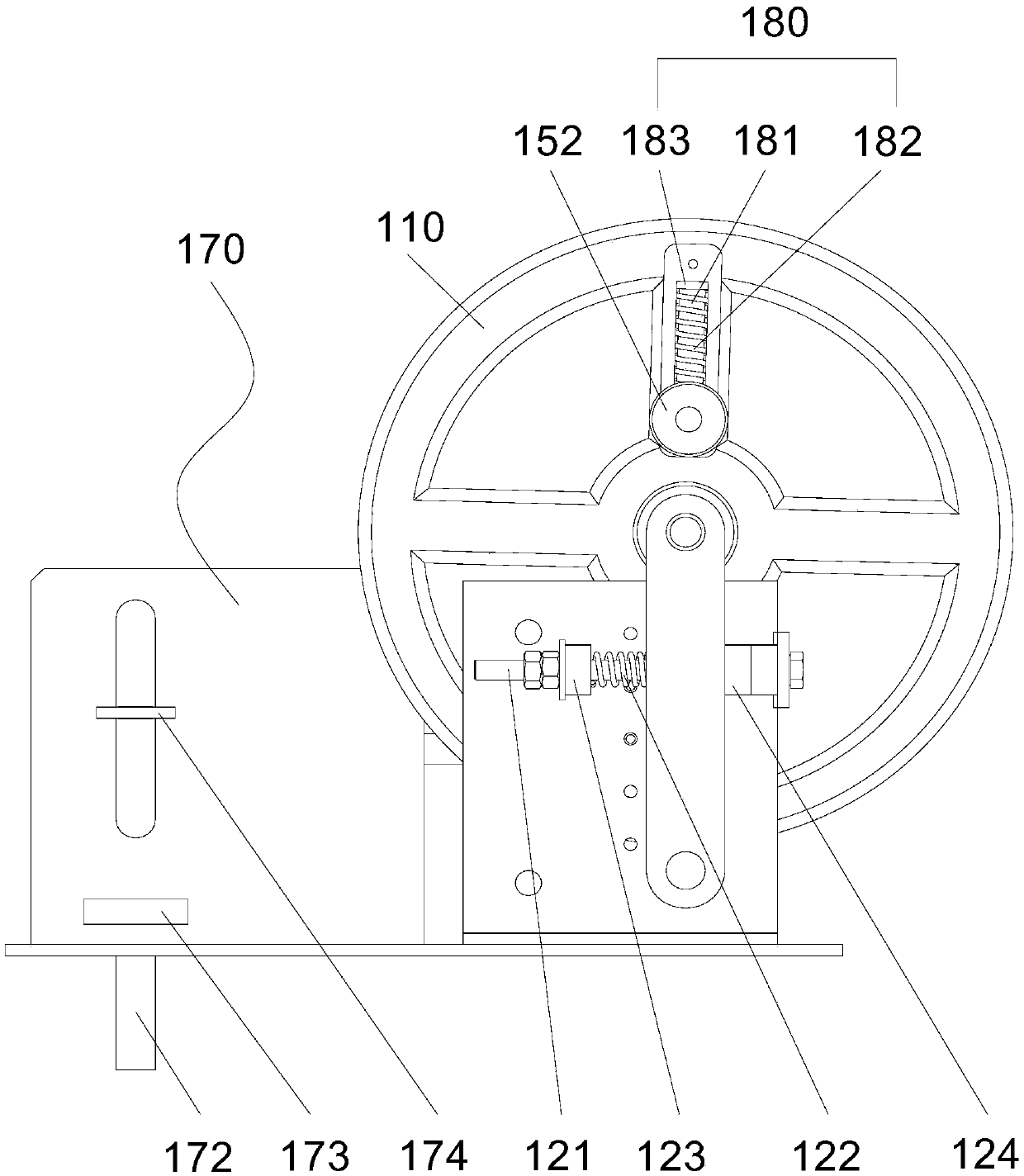
[0044] see figure 1—4, a speed monitoring and braking device 1 of a vertical lifting device, which includes: a roller 110, whose wheel circumference is pressed on the guide rail 4 of the vertical lifting device; The car body 2 of the vertical lifting device is connected; the centrifugal block 150 is movably arranged on the roller 110 along the radial direction of the roller 110; the centrifugal block balance mechanism 180 includes a compressible elastic member, preferably a compressible elastic member It is stage clip 182; stage clip 182 is arranged between the wheel circumference of centrifugal block 150 and roller 110; main engine safety switch 160, it comprises the first trigger mechanism that disconnects main engine safety switch 160 after feeling centrifugal block 150, preferably Specifically, the first trigger mechanism is the shift lever 161; the brake trigger device 170 includes: a pull rod 172, which is connected with the safety gear pull device 3; after the centrifug...


PUM


Abstract

The invention discloses a speed monitoring and braking device for vertical lifting equipment. The equipment includes an idler wheel, a rotating shaft, a centrifugal block, a centrifugal block balancing mechanism, a main-engine safety switch and a brake triggering device; the idler wheel tightly presses a guide rail, the rotating shaft is arranged on the idler wheel in a penetrating mode and connected with a carriage body, the centrifugal block can be movably arranged on the idler wheel in the radial direction of the idler wheel, the centrifugal block balancing mechanism includes a compressibleelastic part, the compressible elastic part is arranged between the centrifugal block and the circumference of the idler wheel, and after the centrifugal block is sensed, a first trigger mechanism ofthe main-engine safety switch is switched off; the brake triggering device includes a lifting rod and a second triggering mechanism, the lifting rod is connected with a safety gear lifting device, and after the centrifugal block is sensed, the second triggering mechanism of the lifting rod is triggered; in the radial direction of the idler wheel, the second triggering mechanism is farther away from the rotating shaft than the first triggering mechanism. According to the speed monitoring and braking device for the vertical lifting equipment, the situation that the use cost increases due to theincrease of the lifting height is avoided, when a steel wire rope is completely disconnected, effective braking can also be achieved, and no extra space for a machine rood and a wellhole is needed.

Description

technical field [0001] The invention relates to the technical field of vertical lifting equipment, in particular to a speed monitoring and braking device for vertical lifting equipment. Background technique [0002] Vertical lifting equipment is widely used in industry and life, and it is popular among users for its advantages of being able to efficiently and quickly carry out transportation operations in vertical spaces. With the development of social economy, vertical lifting equipment will be more widely used. One of the features of vertical lift equipment that has attracted much attention is safety. How to ensure that the vertical lifting equipment does not cause safety accidents in extreme situations has always been a topic that the industry is constantly striving to improve. [0003] At present, the safety guarantee measures for vertical lifting equipment are usually to install a speed limiter at the top floor of the equipment room or the running shaft, and install a...

Claims


Application Information

Patent Timeline
Patent Type & Authority Applications(China)
IPC IPC(8): B66B5/00B66B5/04B66B5/16B66F7/00
CPCB66B5/0031B66B5/044B66B5/16B66F7/00
Inventor 李观亮谭峥嵘陈健豪黄文邓耀焜
Owner GUANGZHOU GUANGRI ELEVATOR IND
Why Eureka
Try Eureka